Electroconductive roller and a method of manufacturing a electroconductive roller

Inactive Publication Date: 2005-09-15
SUMITOMO RUBBER IND LTD +1
View PDF3 Cites 20 Cited by
  • Summary
  • Abstract
  • Description
  • Claims
  • Application Information

AI Technical Summary

Benefits of technology

[0108] The electroconductive roller of the present invention has the electroconductive cellular material layer in which foamed cells are fine and uniform in the diameter thereof. Further the electroconductive roller has a low and uniform hardness and little variations in its electric resistance. Thus the electroconductive roller provides a uniform image. In addition, although fine toner is used, toner contamination can be prevented. Further the electroconductive roller provides an image having a resolution corresponding to the diameter of toner. Therefore the electroconductive roller is capable of coping with the present tendency of using fine toner. Furthermore the electroconductive cellular material layer of the present invention is made of the polyurethane composition and does not contain a chlorine-containing material or a bromine-containing material such as epichlorohydrin rubber. Thus there is no fear that the electroconductive roller contaminates environment when it is burnt for disposal and the electroconductive roller can be disposed at a lost cost. In particular, the electroconductive roller is preferable because it does not contain the chlorine-containing material, the bromine-containing material, and a heavy metal-containing material.
[0109] In the conventional electroconductive roller having the electroconductive cellular material layer, when a foam is formed in a mold havi

Problems solved by technology

Unless the foamed cells become finer as the toner becomes finer, the electroconductive roller is contamin

Method used


Image

  • Electroconductive roller and a method of manufacturing a electroconductive roller
  • Electroconductive roller and a method of manufacturing a electroconductive roller
  • Electroconductive roller and a method of manufacturing a electroconductive roller

Examples


synthesis example 1 through 3

OF URETHANE PREPOLYMER

[0130] Reaction was made among the components used at the ratios shown in the table shown below to synthetically prepare the urethane prepolymer in a reaction container from which water was eliminated. The reaction period of time was three hours. The reaction temperature was 80° C.

Synthesis example of urethane prepolymerSynthesisSynthesisSynthesisexample 1example 2example 3Polyether polyol (molecular weight:2100210021006000, trifunctional, mol ratiobetween ethylene oxide andpropylene oxide = 2:8)Silicon modified polyol (molecular2424weight: 2400, bifunctional,polyorganosiloxane-terminated polyether glycol)Isophorone diisocyanate2372324,4-diphenylmethane diisocyanate292Dibutyltin dilaurate0.10.10.1Diisononyl phthalate250NCO %1.81.82.2Viscosity (mPa · s)440004600065000

PREPARATION EXAMPLE (LATENT CURING AGENT)

[0131] 30 parts by weight of titanium dioxide powder having a diameter of 0.3 μm and 100 parts by weight of 1,12 dodecanediamine (melting point: 71° C.) h...

example 1 through 4

OF MANUFACTURING THERMOSETTING ONE-PART URETHANE COMPOSITION

[0132] The thermosetting one-part urethane composition was obtained by using the urethane prepolymer of the synthesis example 1 through 3 and the latent curing agent of the preparation example used at the ratios shown in the table shown below.

Example of manufacturing thermosetting one-part urethane compositionManufacturingManufacturingManufacturingManufacturingCompoundexample 1example 2example 3example 4Synthesis example 1 of prepolymer100100Synthesis example 2 of prepolymer100Synthesis example 3 of prepolymer100CrosslinkingPolymethylene polyphenyl polyisocyanate1111agentLatentShown in “Preparation example”7.27.27.28.6curing agentSurfacePolyether modified polyorganosiloxane0.5active agentFillerPowdered acrylate copolymer (average101010polymerization degree: 2000, averageparticle diameter: 1 μm)ColoringCarbon black0.50.50.50.5agentCatalyst1,8-(diazabicyclo(5,4,0)undecene-7,0.10.10.1p-toluenesulfonateCatalystDibutyltin bisa...

example 1

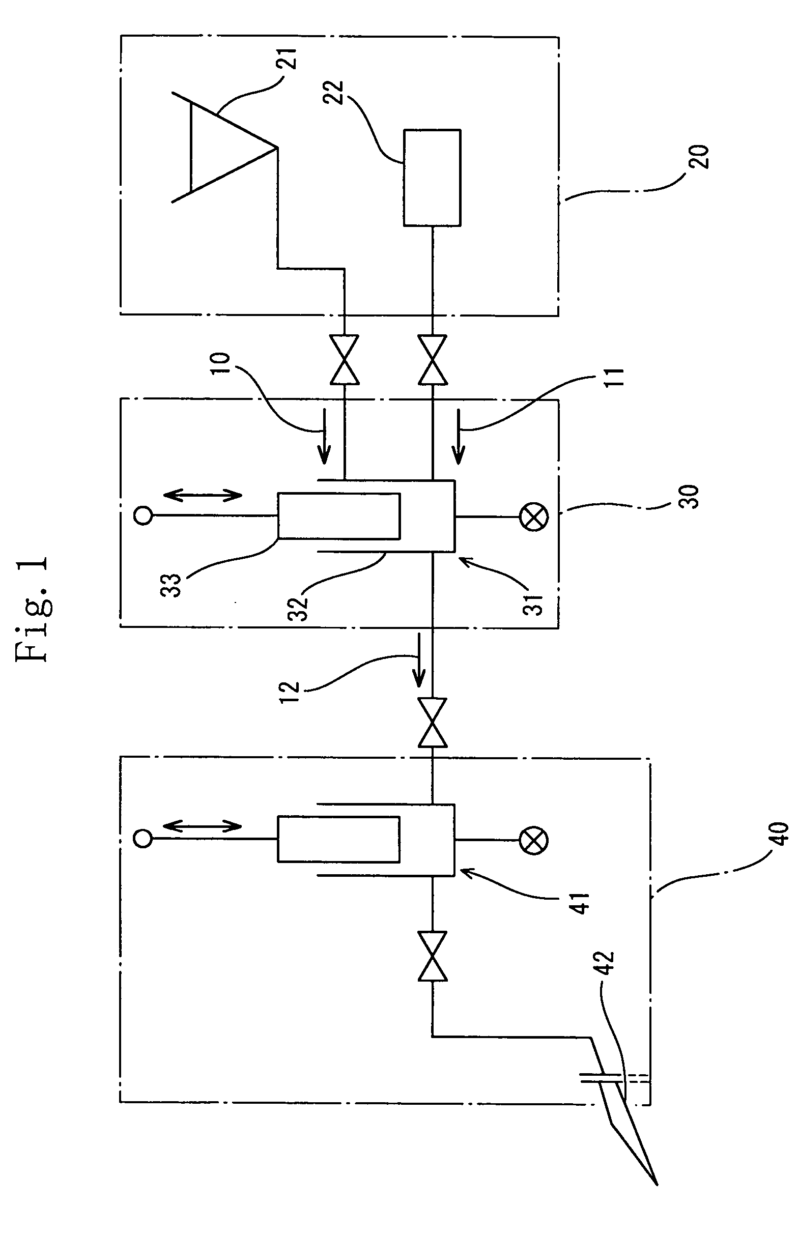
[0133] The foamable thermosetting one-part polyurethane composition was formed by using the foaming apparatus shown in FIG. 1.

[0134] More specifically, after the suction step of the piston pump 31 disposed inside the mixing apparatus 30 is performed, dry air 11 was introduced from the gas supply source 22 into the cylinder 32 of the piston pump 31 decreased to a low pressure by the piston 33. After the dry air 11 was introduced into the cylinder 32, the thermosetting one-part polyurethane composition 10 was introduced from the thermosetting one-part polyurethane composition supply source 21 into the cylinder 32 accommodating the dry air 11. Thereafter the discharge step of the piston pump 31 was performed to obtain the foamable thermosetting one-part polyurethane composition 12 containing the thermosetting one-part polyurethane composition 10 mixed with the dry air 11.

[0135] The foamable thermosetting one-part polyurethane composition 12 was injected into a mold from the tip of th...


PUM

PropertyMeasurementUnit
Temperatureaaaaaaaaaa
Lengthaaaaaaaaaa

Abstract

An electroconductive roller including an electroconductive cellular material layer, comprised of a polyurethane composition, which has an average foamed cell diameter not more than 100 μm and a variation ΔD of the foamed cell diameter not more than 50 μm. The electroconductive roller has a hardness variation ΔHs not more than 8 degrees and a circumferential non-uniformity index RMAX/RMIN in an electric resistance thereof not more than 1.3. The electroconductive cellular material layer is made of a thermosetting one-part polyurethane composition. And the polyurethane composition is cured instantly at a temperature not less than a thermosetting critical temperature for curing thereof, after it is foamed by a mechanical foaming method.

Description

[0001] This nonprovisional application claims priority under 35 U.S.C. § 119(a) on Patent Application No(s). 2004-066426 filed in Japan on Mar. 9, 2004, the entire contents of which are hereby incorporated by reference. BACKGROUND OF THE INVENTION [0002] 1. Field of the Invention [0003] The present invention relates to an electroconductive roller having an electroconductive cellular material layer comprised of a polyurethane composition. Particularly, the present invention relates to an electroconductive roller having a small diameter in foamed cells thereof, a small variation width in the diameter in the foamed cells thereof, a small variation width in the hardness thereof, and a small variation width in the electric resistance thereof. More particularly, the present invention relates to a roller whose electroconductive cellular material layer is composed of a thermosetting one-part polyurethane composition with which a gas is mechanically mixed, a method of manufacturing the elect...

Claims


Application Information

Patent Timeline
IPC IPC(8): G03G15/08B25F5/02B29C39/10B29C44/00B29K75/00B29K105/22B29L31/32C08J9/04C08L75/04F16C13/00G03G5/00G03G15/00G03G15/02G03G15/16
CPCB29C44/38Y10T428/1376B29K2075/00B29K2105/04C08G18/10C08G18/12C08G18/168C08G18/1866C08G18/246C08G18/4009C08G18/4837C08G18/61C08G18/755C08G18/7671C08G2101/00C08K2201/001C08L75/04G03G5/0525G03G5/0575G03G5/0589G03G5/0592G03G5/0596G03G5/10G03G2215/025G03G2215/0863B29C67/246Y10T29/49563C08G18/7664C08L33/04G03G2215/1614
Inventor HATTORI, TAKAYUKIUESAKA, KENICHIOCHI, JUNNISHIBAYASHI, JUNBESSYO, SHINJITANAKA, SATOSHITAKADA, MASAHARUOKUDA, SHINJI
Owner SUMITOMO RUBBER IND LTD
Why Eureka
Try Eureka