Fluorescent endoscope system having improved image detection module

a fluorescent endoscope and image detection technology, applied in the field of fluorescent endoscope system and imaging diagnostic objects, can solve the problems of lower sensitivity and the inability of the observer (e.g., the physician) to correctly recognize the source of fluorescent light, and achieve the effect of reducing frame loss and efficient composition and display of superimposed images

Active Publication Date: 2005-09-15
INTHESMART
View PDF12 Cites 60 Cited by
  • Summary
  • Abstract
  • Description
  • Claims
  • Application Information

AI Technical Summary

Benefits of technology

[0014] Accordingly, the present invention has been made to solve the above-mentioned problems occurring in the prior art, and an object of the present invention is to provide an improved fluorescent endoscope system having first and second optical detection chips integrated in a single camera module to obtain images of excited reflection light and fluorescent light with the same timing for minimized frame loss and efficient composition and display of superimposed images.
[0015] Another object of the present invention is to provide a fluorescent endoscope system capable of compensating for the change of fluorescent intensity, which depends on the distance from the diagnostic object to the distal end of the endoscope module, using signals of reflected excitation light for accurate diagnosis independent of the distance.
[0017] Another object of the present invention is to provide an improved fluorescent endoscope system having reduced factors that cause errors during diagnosis based on quantitative evaluation of fluorescent intensity for improved accuracy of fluorescent endoscopic diagnosis.

Problems solved by technology

The optical filter is designed in such a manner that a part of the reflected excitation light reaches the camera detector because, if the reflected excitation light is completely interrupted, the observer (e.g., a physician) cannot correctly recognize from where fluorescent light is generated.
However, the above-mentioned conventional fluorescent endoscope system has problems as follows: the color TV camera of the fluorescent endoscope system, which basically has lower sensitivity than monochrome cameras, cannot accurately perceive faint fluorescent light emitted from the diagnostic object and, in particular, cannot be used when an endoscope having a small aperture ratio is necessary.
Furthermore, optical noise increases and faint fluorescent light cannot be perceived, because reflected excitation light is partially transmitted.
In summary, poor sensitivity to fluorescent light and existence of optical noise make diagnosis through quantitative fluorescent observation impossible.
If the reflected excitation light is partially transmitted to the high-sensitivity optical detection chip for sensing fluorescent light to this end, however, the accuracy of quantitative analysis deteriorates.
Although the above fluorescent endoscope system according to the prior art uses two cameras to separately detect reflected excitation light and fluorescent light for improved accuracy of quantitative analysis, the cameras are operated asynchronously and, when image signals of reflected excitation light and fluorescent light obtained from both asynchronously operated cameras are successively inputted to a computer via a PCI bus, a number of frames are lost due to difference in frame timing.
When signals obtained from different cameras are separately processed according to the prior art, however, such coincidence is difficult to occur.
Such mechanical maintenance of distance is vulnerable to errors resulting from diagnostic environments (e.g., fine vibration) and has limited diagnostic accuracy.
This makes the system very complicated.

Method used


Image

  • Fluorescent endoscope system having improved image detection module
  • Fluorescent endoscope system having improved image detection module
  • Fluorescent endoscope system having improved image detection module

Examples


Embodiment Construction

[0031] Hereinafter, a preferred embodiment of the present invention will be described with reference to the accompanying drawings. In the following description and drawings, the same reference numerals are used to designate the same or similar components, and so repetition of the description on the same or similar components will be omitted.

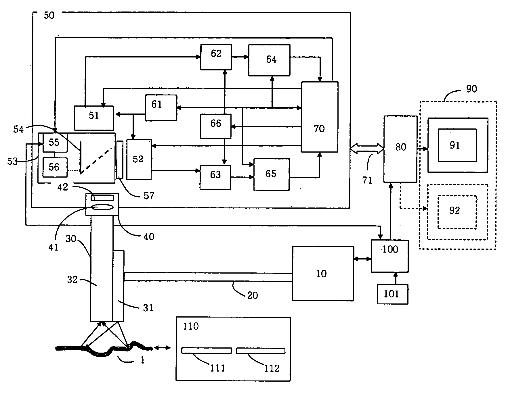
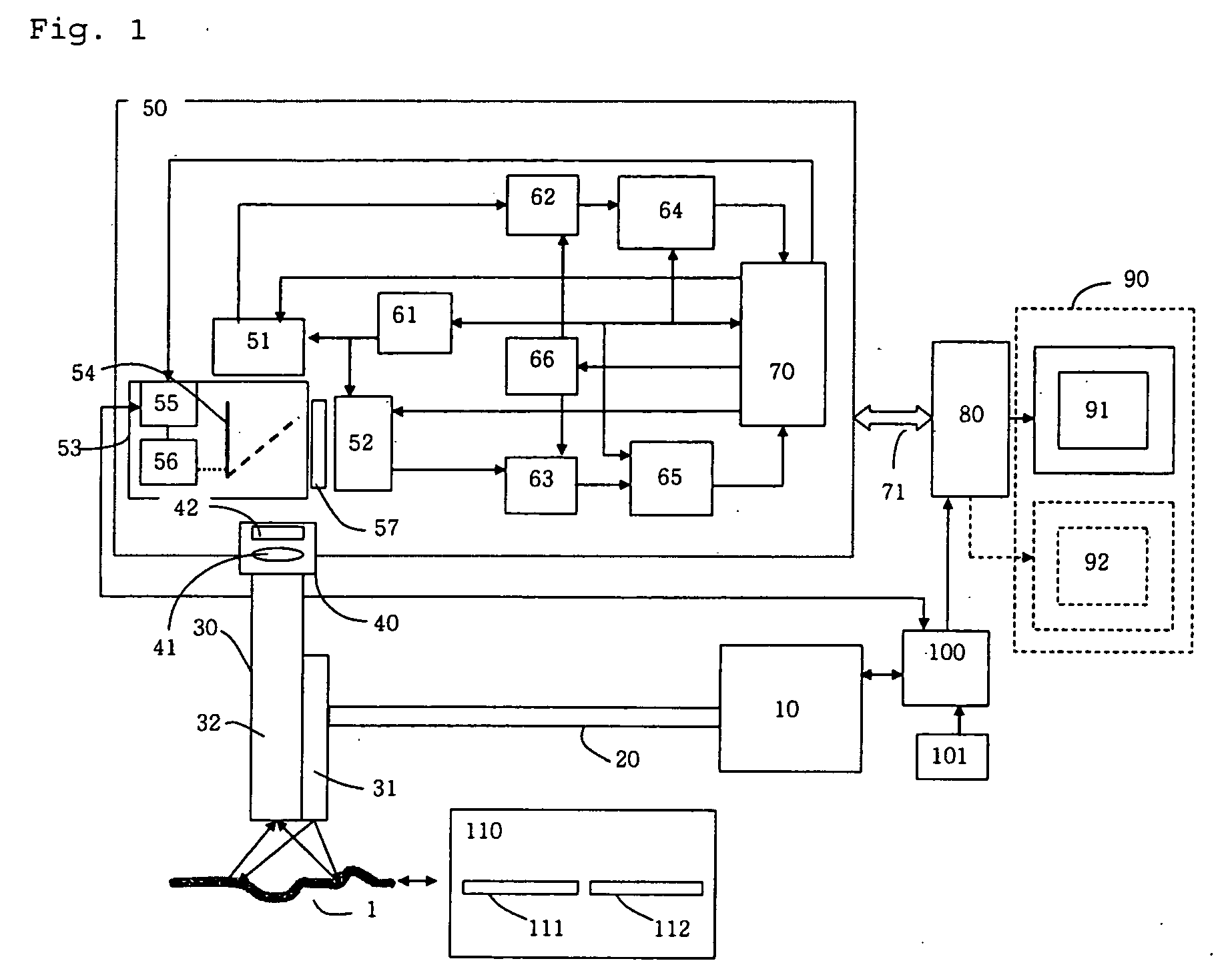
[0032]FIG. 1 is a block diagram showing the construction of a fluorescent endoscope system according to a preferred embodiment of the present invention. The fluorescent endoscope system includes a composite optical source module 10 connected to an optical source cable 31 provided in the endoscope. The composite optical source module 31 uses incoherent light as an optical source and provides white light for normal visual observation of a diagnostic object 1 (in a normal endoscope mode) or short-wavelength light for fluorescent excitation to simultaneously observe fluorescent light and reflected excitation light (in a fluorescent observation mode)...


PUM


Abstract

Disclosed is an improved fluorescent endoscope system having reduced factors that cause errors during diagnosis based on quantitative evaluation of fluorescent intensity for improved accuracy of fluorescent endoscopic diagnosis. The fluorescent endoscope system includes an optical source module for providing white light or excitation light; an endoscope assembly having an optical transmission path for transmitting light provided from the optical source module to a diagnostic object and an optical detection module for transmitting reflection light and fluorescent light from the diagnostic object; an optical path split means for splitting the path of the reflection light and fluorescent light transmitted from the endoscope assembly; and a two-chip integration image detection module having a first optical detection chip for detecting the reflection light and outputting a first optical detection signal, a second optical detection chip for detecting the excitation light and outputting a second optical detection signal, a gain control unit for controlling a signal amplification gain value to adjust the brightness of an image detected by the first optical detection chip, a first amplification unit for amplifying the first optical detection signal according to the signal amplification gain value, and a second amplification unit for amplifying the second optical detection signal according to a changing ratio of the signal amplification gain value.

Description

BACKGROUND OF THE INVENTION [0001] 1. Field of the Invention [0002] The present invention relates to a fluorescent endoscope system and a method for imaging diagnostic objects using the same, and more particularly to a fluorescent endoscope system having an improved image detection module for accurate and efficient diagnosis of tumors in the human body and a method for imaging in vivo diagnostic objects using the same. [0003] 2. Description of the Prior Art [0004] As generally known in the art, a vesical fluorescent endoscope has been developed by Karl Storz GmgH, Germany, and used for vesical tumor diagnosis. It uses an optical source of white light and provides detailed observation of the surface of an internal organ as a normal endoscope system. Furthermore, it also uses an optical source (e.g., D-LIGHT) of blue light as excitation light, which is composed of a xenon lamp and an optical fiber, and provides fluorescent observation of dubious parts induced by a contrast medium (e.g...

Claims


Application Information

Patent Timeline
Patent Type & Authority Applications(United States)
IPC IPC(8): A61B1/05A61B1/06A61B1/07A61B5/00A61B6/00
CPCA61B1/00009A61B1/043A61B1/05A61B2560/0233A61B5/0071A61B5/0084A61B1/07
Inventor KANG, UKPAPAYAN, GARRY V.
Owner INTHESMART
Why Eureka
Try Eureka