Apparatus and methods for removing vertebral bone and disc tissue

a technology for disc tissue and vertebral bone, applied in the field of medical devices and methods for removing disc tissue, can solve the problems of disc tissue irreparably damaged, pain, and even prolonged disability, and achieve the effect of reducing stray lines and steadier cutting action of tissue removal elements

Active Publication Date: 2005-09-15
BOSTON SCI SCIMED INC
View PDF59 Cites 172 Cited by
  • Summary
  • Abstract
  • Description
  • Claims
  • Application Information

AI Technical Summary

Benefits of technology

[0023] In accordance with a first aspect of the present invention, the tissue removal element comprises a plurality of tissue-cutting filaments affixed at proximal and distal ends of the tissue removal element. In one embodiment, the tissue removal element comprises a base member mounted to the distal end of the drive shaft and a distal hub. The filaments are connected between the base member and the distal hub. The filaments can be variously configured. In one embodiment, the filaments are interlaced, e.g., to provide the tissue removal element with increased structural integrity. In another embodiment, the filaments are looped. The tissue removal element may further include abrasive particles disposed on the filaments. The tissue removal probe optionally comprises a proximal adapter mounted to the member for mating with a drive unit. The tissue removal probe may optionally comprise a guide wire extending through the tissue removal element in order to provide lateral support. By way of non-limiting example, the large spaces formed between the tissue-cutting filaments prevents or minimizes the build up of tissue on the tissue removal element.
[0025] In accordance with a third aspect of the present inventions, the drive shaft is rigid and has a distal end with a blunt tip, e.g., a spherical tip. In this manner, inadvertent tissue trauma distal to the tissue removal element is prevented or minimized. The tissue removal probe further comprises a lumen extending through the drive shaft and terminating in a flush port at the blunt tip. In this manner, a convenient means of providing irrigation fluid to the tissue and / or tissue removal element is provided. The tissue removal element can take the form of any element, but in one embodiment, it is an abrasive burr. A spiral cutting groove can be provided on the tissue removal element, so as to facilitate movement of the removed tissue in the proximal direction. The optional proximal adapter may be configured for mating with both a drive unit and an irrigation source.
[0028] The tissue removal elements may take the form of any element, but in one embodiment, they take the form of two separate burrs. The tissue removal elements may advantageously have oppositely pitched spiral cutting grooves. In this manner, when rotated in opposite directions, the cutting action of the tissue removal elements is steadier, and minimizes stray from the cutting line. When rotated in the same direction, the removed tissue is forced to travel along the cutting grooves to the interface between the tissue removal elements, where it can be collected and aspirated.

Problems solved by technology

In some cases, however, the disc tissue is irreparably damaged, in which case, surgery is the best option.
VCFs are common in patients who suffer from these medical conditions, often resulting in pain, compromises to activities of daily living, and even prolonged disability.
A physician may have difficulty controlling existing bone removal devices, however, and may unintentionally remove healthy bone tissue or injure spinal tissue during use.
This problem is exacerbated with percutaneous treatments, which, although less invasive than other procedures, limit the range of motion of the cutting instrument, thereby further limiting the control that the physician may have during the bone cutting procedure.
As can be appreciated, this excessive movement of the removal device 60 increases the time of the spinal procedure as well as surgical risk due to manipulation of the device.
Another problem with current burr-type removal devices is that soft material, such as the nuclear material in an intervertebral disc or cancellous bone within the vertebral body, tends to stick to the burrs, thereby limiting the abrasive effect that the burrs are intended to have in order to efficiently remove tissue.
As a result, the incision through which the cannula is to be introduced must be made relatively large, thereby unnecessarily causing more tissue trauma.

Method used


Image

  • Apparatus and methods for removing vertebral bone and disc tissue
  • Apparatus and methods for removing vertebral bone and disc tissue
  • Apparatus and methods for removing vertebral bone and disc tissue

Examples


Embodiment Construction

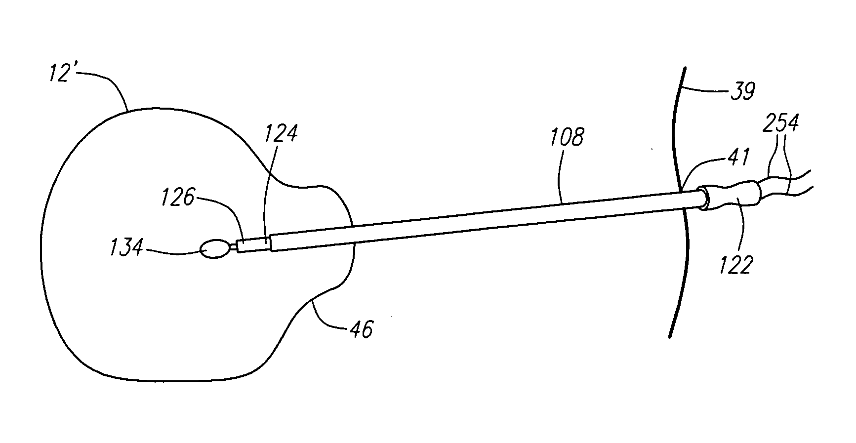
[0067]FIG. 8 illustrates a tissue removal system 100 constructed in accordance with a preferred embodiment of the present inventions. The system 100 generally comprises a tissue removal probe assembly 102 and a rotary drive unit 104 connected to the probe assembly 102 via a drive cable 106. The drive unit 104 may take the form of a standard rotary drive used for powering medical cutting instruments. The tissue removal probe assembly 102 comprises a cannula 108 and a tissue removal probe 110 disposed therein.

[0068] The cannula 108 comprises a shaft 112 having a distal end 114 and proximal end 116, a lumen 118 (shown in phantom) terminating in an exit port 120 at the distal end 114 of the cannula shaft 112, and a handle 122 mounted on the proximal end 116 of the cannula shaft 112. To facilitate introduction through tissue, the cannula shaft 112 is preferably stiff (e.g., it can be composed of a stiff material, or reinforced with a coating or a coil to control the amount of flexing), ...


PUM


Abstract

Tissue removal probes comprise an elongated member, a drive shaft rotatably disposed within the member, and a rotatably tissue removal element mounted to the distal end of the drive shaft. One tissue removal element comprises a plurality of tissue-cutting filaments affixed at proximal and distal ends of the tissue removal element. The cutting filaments may have optional hinge points that allow the distal end of the tissue removal element to be inverted, thereby transforming the tissue removal element from a tissue-cutting device to a tissue-grasping device. Another tissue removal element may have a blunted tip to prevent distal tissue trauma and an irrigation port to provide irrigation fluid to the removed tissue and / or tissue removal element. Another tissue removal element has a proximal and distal spiral grooves that are oppositely pitched, so that removed tissue can be collected in the middle of the tissue removal element. Another tissue removal element has independent counter-rotating tissue removal elements to maintain stability during a bone cutting procedure. Still another tissue removal element takes the form of a drill bit with fluted cutting grooves. Yet another tissue removal element has cascading tissue-cutting notches that can be reciprocatably moved to remove tissue within a hole.

Description

RELATED APPLICATIONS [0001] This application is related to copending applications Ser. No. 10 / ______ (Attorney Docket No. 2024730-7036832001), Ser. No. 10 / ______ (Attorney Docket No. 2024730-7036842001) and Ser. No. 10 / ______ (Attorney Docket No. 2024730-7038292001), which is expressly incorporated herein by reference. FIELD OF THE INVENTION [0002] The field of the invention pertains to medical devices and methods for removing tissue, and in particular, vertebral bone and intervertebral disc tissue. BACKGROUND OF THE INVENTION [0003] The spinal column consists of thirty-three bones called vertebra, the first twenty-four vertebrae of which make up the cervical, thoracic, and lumbar regions of the spine and are separated from each other by “pads” of tough cartilage called “intervertebral discs,” which act as shock absorbers that provide flexibility, stability, and pain-free movement of the spine. [0004]FIGS. 1 and 2 illustrate a portion of a healthy and normal spine, and specifically,...

Claims


Application Information

Patent Timeline
Patent Type & Authority Applications(United States)
IPC IPC(8): A61B17/00A61B17/16A61B17/22A61B17/32A61M1/00
CPCA61B17/1604A61B2217/005A61B17/1617A61B17/1631A61B17/1633A61B17/1662A61B17/1671A61B17/221A61B17/32002A61B17/320725A61B2017/00261A61B2017/003A61B2017/22038A61B2017/320032A61B17/1615A61B2017/320028A61B2217/007
Inventor CARRISON, HAROLD F.PATEL, MUKUND R.OLSON, STANLEY W. JR.
Owner BOSTON SCI SCIMED INC
Why Eureka
Try Eureka