Digital radio receiver

a radio receiver and digital technology, applied in the field of digital radio receivers, can solve the problems of inability to achieve the same distance, and inability to reliably recover original information, so as to reduce the complexity of the receiver, reduce the cost, and simplify the structure and cost-effective

Inactive Publication Date: 2005-09-22
OKI TECHNO CENT SINGAPORE PTE
View PDF7 Cites 47 Cited by
  • Summary
  • Abstract
  • Description
  • Claims
  • Application Information

AI Technical Summary

Benefits of technology

[0017] The present invention provides a phase offset compensator with simpler structure and cost-effectiveness to replace the conventional

Problems solved by technology

However, inaccuracies in the oscillators of the transmitter and receiver and the effect of Doppler shifting lead to carrier frequency offsets which make this approach infeasible.
If the frequency offset is excessive and not adequately compensated, the performance of the demodulator will invariably be degraded to an extent that the original information cannot be reliably recovered.
Although quite effective in reducing the carrier frequency offset of a received signal, the PLL based technique is fairly complex as it involves the design of a Numerically Controlled Oscillator (NCO) for sinusoidal waveform generation.
Depending on the required accuracy, the iteration time may be too long, thereby contributing to longer PLL loop delay and causing potential instability.
Furthermore, the PLL based technique is highly susceptible to input signal amplitude fluctuation and can degrade the overall receiver

Method used


Image

  • Digital radio receiver
  • Digital radio receiver
  • Digital radio receiver

Examples


first embodiment

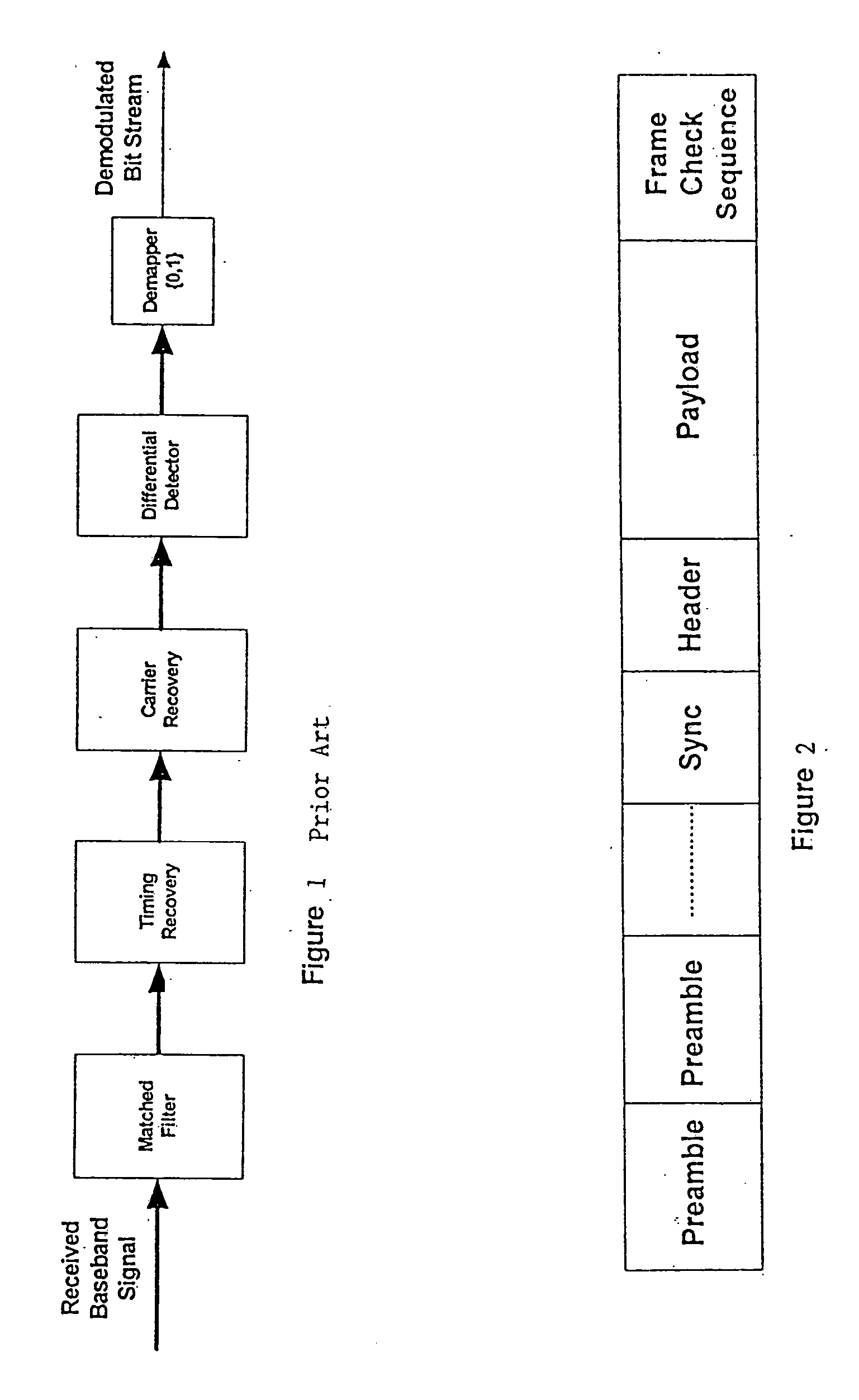
[0036]FIG. 2 shows a packet format of a signal received by a receiver of the present invention. It comprises repetitive preamble sequences to aid the receiver algorithms for Automatic Gain Controlled (AGC) control, timing recovery, phase-offset recovery and signal equalization. A Synchronization Pattern (Sync) is also included to aid frame synchronization so that relative positions of Header and Payload can be determined.

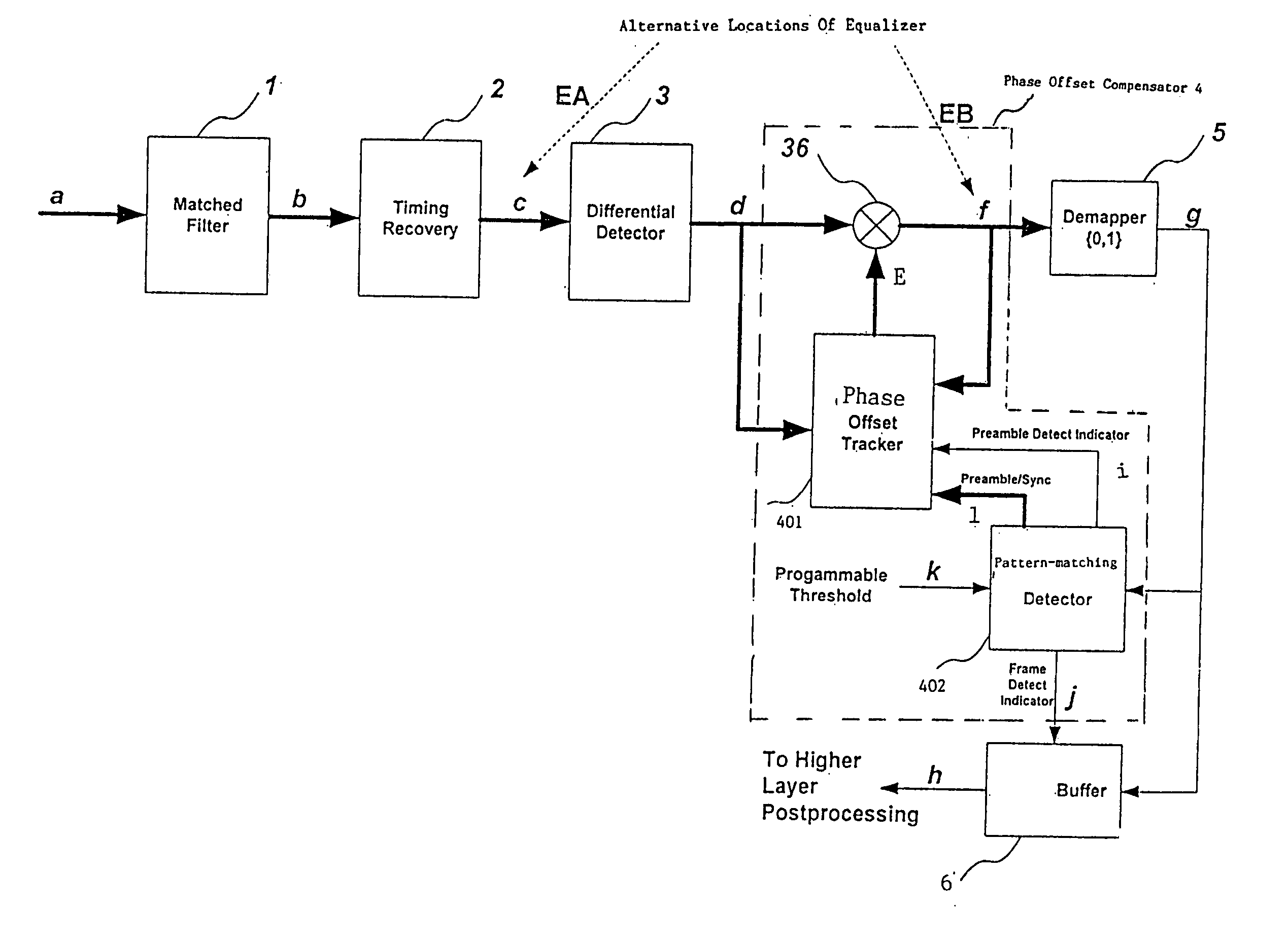
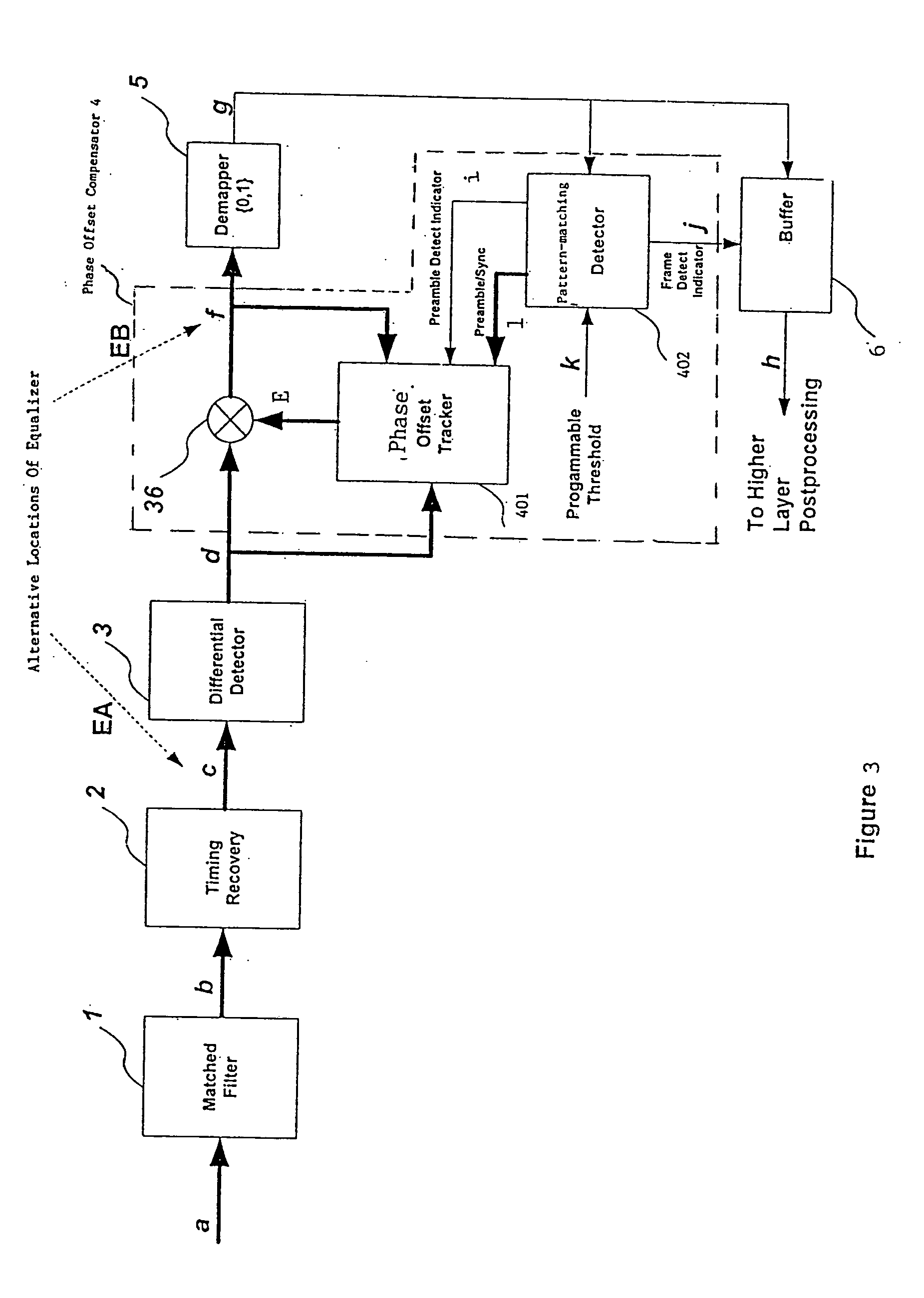
[0037]FIG. 3 schematically illustrates a first embodiment of a receiver of the present invention. The received signal (through line a) is first filtered through a Matched Filter 1, typically a square-root-raised cosine filter. The filtered signal (through line b) is then coupled to a Timing Recovery Loop 2. As mentioned before, the Timing Recovery Loop 2 recovers the received symbols so that they are both phase and frequency matched to the transmitter clock. The Timing Recovery Loop 2 outputs the timing-corrected samples at symbol rate to a Differential Detector 3 ...

second embodiment

[0067]FIG. 13 schematically illustrates a second embodiment of a receiver of the present invention. As shown in FIG. 13, the second embodiment of the receiver includes a matched filter 1 for filtering a received signal to remove the out-of-band noise, a timing recovery module 2 for recovering the filtered signal to output timing corrected symbols, a differential detector 3 for differentially demodulating the timing corrected symbols, a phase offset compensator 4 for compensating the phase offset existing in the neighboring detected symbols which includes a phase offset tracker 401, a phase-matching detector 402′ and a multiplier 36, a buffer 6 for storing the phase offset compensated symbols from the compensator 4 and a demapper 5 for decoding the data from the buffer 6. The difference between the first and second embodiments of the receiver of the present invention is the position of the demapper, and the structure of the phase-matching detector 402′, which is modified accordingly ...


PUM


Abstract

A digital radio receiver is disclosed herein. The receiver substitutes a phase offset compensator with a simple and cost-effective structure for the conventional carrier recovery unit which is relatively complex and expensive, so as to decrease the complexity of the receiver and to provide cost savings. The digital radio receiver includes means arranged to filter and timing recover a received signal to produce timing corrected symbols; means arranged to differentially detect the timing corrected symbols; means arranged to compensate a phase offset of the detected symbol; and decoding means arranged to decode the phase offset compensated symbols into a bit stream.

Description

FIELD OF THE INVENTION [0001] This present invention relates to a digital radio receiver for use in M-ary differential phase shift keying (MDPSK) demodulation and Continuous Pulse demodulation schemes. BACKGROUND OF THE INVENTION [0002] Radio-communication systems transmit of information over an air interface by modulating the radio frequency (RF) carrier with information sources. When the signal is received, the receiver attempts to extract the original information therefrom by adopting an appropriate demodulation technique. Demodulating digitally-modulated signals entails the use of an estimated replica of the received carrier frequency for recovering the signal. In an ideal situation, the transmitter generates a carrier signal that exists at some known carrier frequency. The received signals are then demodulated at the receiver using the same known frequency. However, inaccuracies in the oscillators of the transmitter and receiver and the effect of Doppler shifting lead to carrie...

Claims


Application Information

Patent Timeline
IPC IPC(8): H04L27/00H04L27/06H04L27/227
CPCH04L27/2278H04L2027/0095H04L2027/0067H04L2027/0046
Inventor PHANG, PIAO CHUNPOH, BOON KIAT
Owner OKI TECHNO CENT SINGAPORE PTE
Why Eureka
Try Eureka