Method of manufacturing hydrophilic carbon nanotubes

a technology of hydrophilic carbon nanotubes and carbon nanotubes, which is applied in the direction of energy-based chemical/physical/physical-chemical processes, metal/metal-oxide/metal-hydroxide catalysts, and metal/metal-oxide catalysts. it can solve the problems of poor wetting ability toward water and various organic solvents, difficult to disperse in water or various organic solvents, and low chemical activity. it achieves large strain energy, easy to open, and large hydrophili

Inactive Publication Date: 2005-09-29
HONDA MOTOR CO LTD +1
View PDF4 Cites 25 Cited by
  • Summary
  • Abstract
  • Description
  • Claims
  • Application Information

AI Technical Summary

Benefits of technology

[0010] An object of the present invention is to provide a method of manufacturing hydrophilic carbon nanotubes capable of imparting hydrophilicity to carbon nanotubes without damaging the surface of the carbon nanotubes, which overcomes such an inconvenience.
[0013] According to the method of manufacturing of the invention, the hydrophilicity can be imparted without damaging the surface of the carbon nanotubes because a strong oxidizing agent such as sulfuric acid or nitric acid is not used.
[0016] Moreover, the irradiation with the ultraviolet ray may be conducted under the air or under a nitrogen atmosphere, but is preferably conducted in the presence of oxygen and hydrogen. By conducting the irradiation in the presence of oxygen and hydrogen, the above hydrophilic functional groups such as a hydroxyl group (—OH), a carbonyl group (—CO—), an aldehyde group (—CHO), a carboxyl group (—COOH), and the like can be easily introduced into the above carbon nanotubes.
[0018] Moreover, in the manufacturing method of the invention, by the irradiation with the ultraviolet ray, the end part(s) of the carbon nanotubes are opened and thereby further larger hydrophilicity can be imparted to the carbon nanotubes. The end part of the carbon nanotubes are closed with forming a hemispherical structure by incorporating five-membered rings into the six-membered rings in part. As a result, the above end part has large strain energy as compared with the part of tube flank composed of only six-membered rings and hence is unstable. Therefore, the end part of the carbon nanotubes can be easily opened by the irradiation with the ultraviolet ray and the carbon at the opened part reacts with oxygen, nitrogen, hydrogen, and the like present in the neighboring atmosphere to form bonds with the above hydrophilic functional group(s).

Problems solved by technology

However, the carbon nanotubes have a structure where a large number of carbon atoms are continuously bonded and hence is low in chemical activity and poor in wetting ability toward water and various organic solvents.
As a result, the carbon nanotubes have a problem that it is difficult to disperse it in water or various organic solvents.
However, in the wet process using sulfuric acid, nitric acid, or the like as mentioned above, hydrophilicity can be imparted to the carbon nanotubes by bonding the hydrophilic functional group(s) thereto but there arises an inconvenience that the structure of the carbon nanotubes themselves are damaged by the acid.
Moreover, in the above wet process, closest attention should be paid at operations owing to the use of sulfuric acid, nitric acid, or the like and also there may be a possible economical disadvantage in the case that sulfuric acid, nitric acid, or the like is used in a large amount.

Method used


Image

  • Method of manufacturing hydrophilic carbon nanotubes
  • Method of manufacturing hydrophilic carbon nanotubes

Examples


example 1

[0031] In the present example, carbon nanotubes were produced by a chemical vapor deposition method (CVD method). In the chemical vapor deposition method, an Fe catalyst having a particle size of 30 nm supported on an Al2O3 support was first attached onto quartz wool placed in a reactor tube made of quartz glass and the whole was heated to 750° C. under an argon atmosphere. Then, a mixed gas of argon / hydrogen was passed through the reactor tube at a space velocity of 10 cm / second and also hexane as a carbon source was introduced into the reactor tube at a rate of 6 ml / minutes in a state dispersed in the mixed gas of argon / hydrogen. Thus, the hexane introduced into the reactor tube was reacted at 750° C. for 2 hours in the presence of the Fe catalyst. As a result, multilayered carbon nanotubes having a purity of 80% were obtained in the present Example.

[0032] Next, the multilayered carbon nanotubes having a purity of 80% were subjected to hot oxidation treatment at 500° C. for 20 mi...

example 2

[0040] In the present Example, hydrophilic carbon nanotubes were produced in exactly the same manner as in Example 1 except that the time for the irradiation with the ultraviolet ray was changed to 60 seconds.

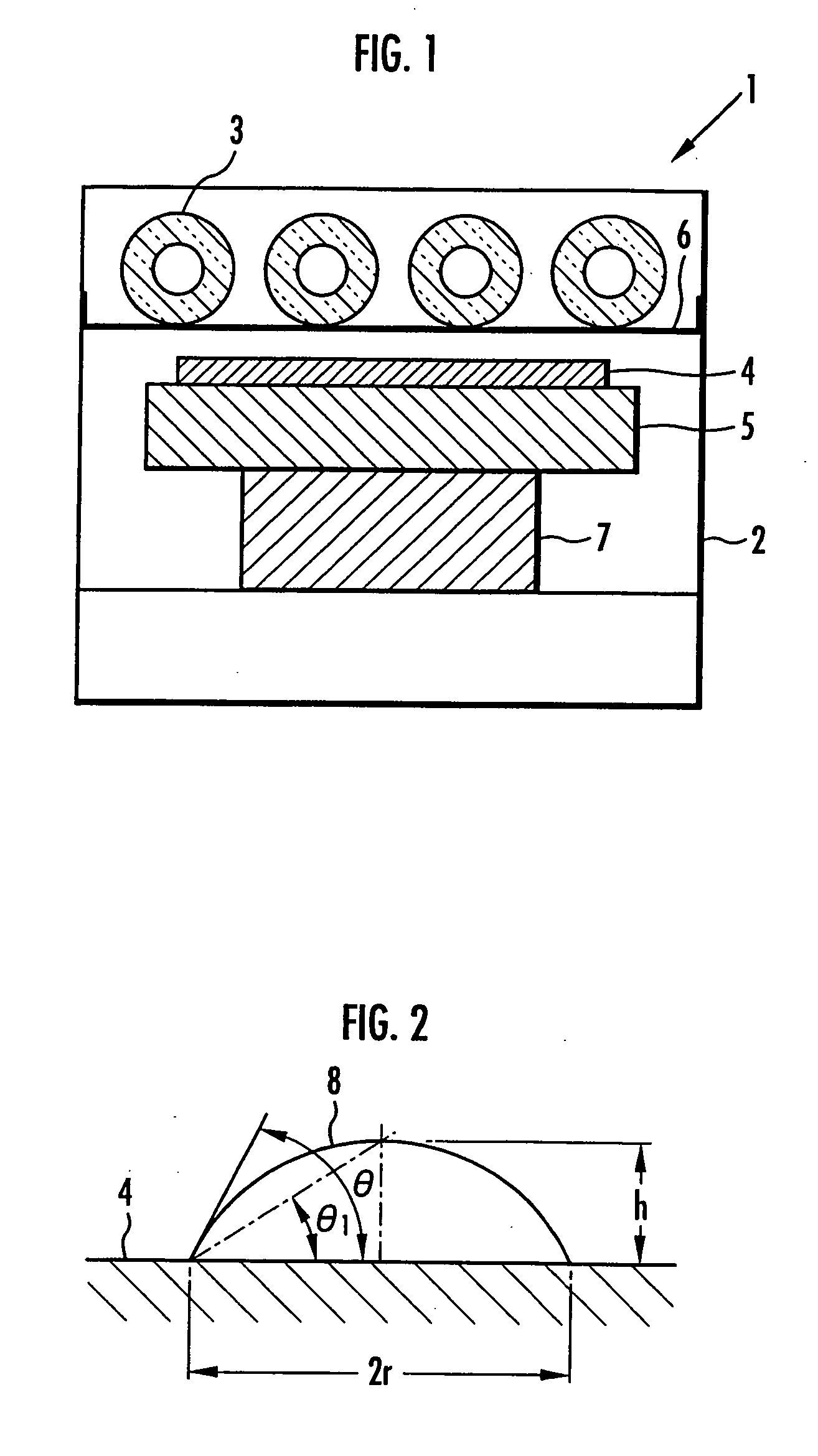
[0041] On the hydrophilic carbon nanotubes thus obtained, a contact angle θ was measured in exactly the same manner as in Example 1. In the present Example, the distilled water dropped on the surface of the disk of the hydrophilic carbon nanotubes soaked into the above disk within 1 second and thus the contact angle θ was 0°. The results are shown in Table 1.

example 3

[0042] In the present Example, hydrophilic carbon nanotubes were produced in exactly the same manner as in Example 1 except that the atmosphere in chamber 2 was made a nitrogen atmosphere and the time for the irradiation with the ultraviolet ray was changed to 60 seconds.

[0043] On the hydrophilic carbon nanotubes thus obtained, a contact angle θ was measured in exactly the same manner as in Example 1, whereby the contact angle θ was found to be 110°. The results are shown in Table 1.


PUM

PropertyMeasurementUnit
contact angleaaaaaaaaaa

Abstract

There is provided a method of manufacturing hydrophilic carbon nanotubes, which is capable of imparting hydrophilicity without damaging the surface of the carbon nanotubes. By irradiating carbon nanotubes 4 with ultraviolet ray 3, hydrophilic functional group(s) are introduced into the surface of carbon nanotubes 4. Hydrophilicity is imparted to the carbon nanotubes to such an extent that a contact angle of water is in the range of less than 130°. Ultraviolet ray 3 is a far ultraviolet ray having a wavelength ranging from 1 to 190 nm. The irradiation with ultraviolet ray 3 is conducted in the presence of oxygen and hydrogen or in the presence of ozone and hydrogen. The end part(s) of carbon nanotubes 4 is opened by the irradiation with ultraviolet ray 3.

Description

BACKGROUND OF THE INVENTION [0001] 1. Field of the Invention [0002] The present invention relates to a method of manufacturing hydrophilic carbon nanotubes. [0003] 2. Description of the Related Art [0004] A carbon nanotube is a single tubular molecule where a large number of carbon atoms are continuously bonded in such a state that six-membered rings are formed by sp2 bonding and possesses a structure of nanometer order. The end part of the carbon nanotube is closed with forming a hemispherical structure by incorporating five-membered rings in part. Moreover, the above carbon nanotubes form single-layered tubes, or tubes of various sizes are sometimes layered in a nested form to form multi-layered tubes. [0005] The above carbon nanotubes are expected to have application to various uses such as one-dimensional wires, catalysts, cold-cathode elements, and hydrogen storage substances owing to mechanical and structural properties derived from its specific structure. However, the carbon ...

Claims


Application Information

Patent Timeline
Patent Type & Authority Applications(United States)
IPC IPC(8): B01J19/12B01J23/745C01B31/02
CPCB01J19/123B01J23/745B01J35/006B82Y30/00B82Y40/00C01B2202/36C01B31/0273C01B2202/06C01B2202/30C01B2202/34C01B31/0233Y10S977/847Y10S977/848C01B32/162C01B32/174
Inventor OHASHI, TOSHIYUKISUGAHARA, HIROSHIMITAMA, MITSUAKI
Owner HONDA MOTOR CO LTD
Why Eureka
Try Eureka