Magnetron oscillating apparatus
a technology of magnetic oscillating apparatus and magnetron, which is applied in the direction of oscillation generators, electric discharge tubes, magnets, etc., can solve the problems of difficult micropatterning for a line width of 1 m or less, abnormal side etching or dielectric breakdown, etc., and achieve high plasma density and reduce the electron temperature of plasma
- Summary
- Abstract
- Description
- Claims
- Application Information
AI Technical Summary
Benefits of technology
Problems solved by technology
Method used
Image

Examples
first embodiment
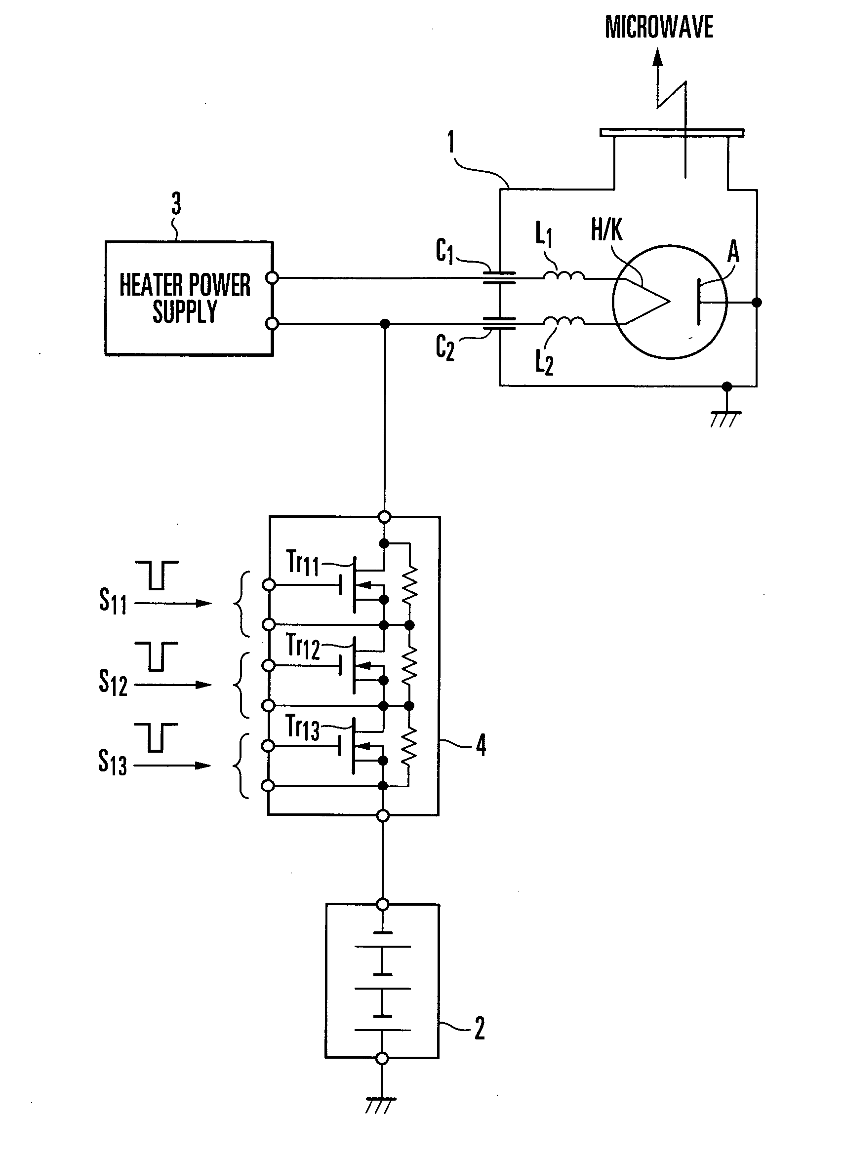
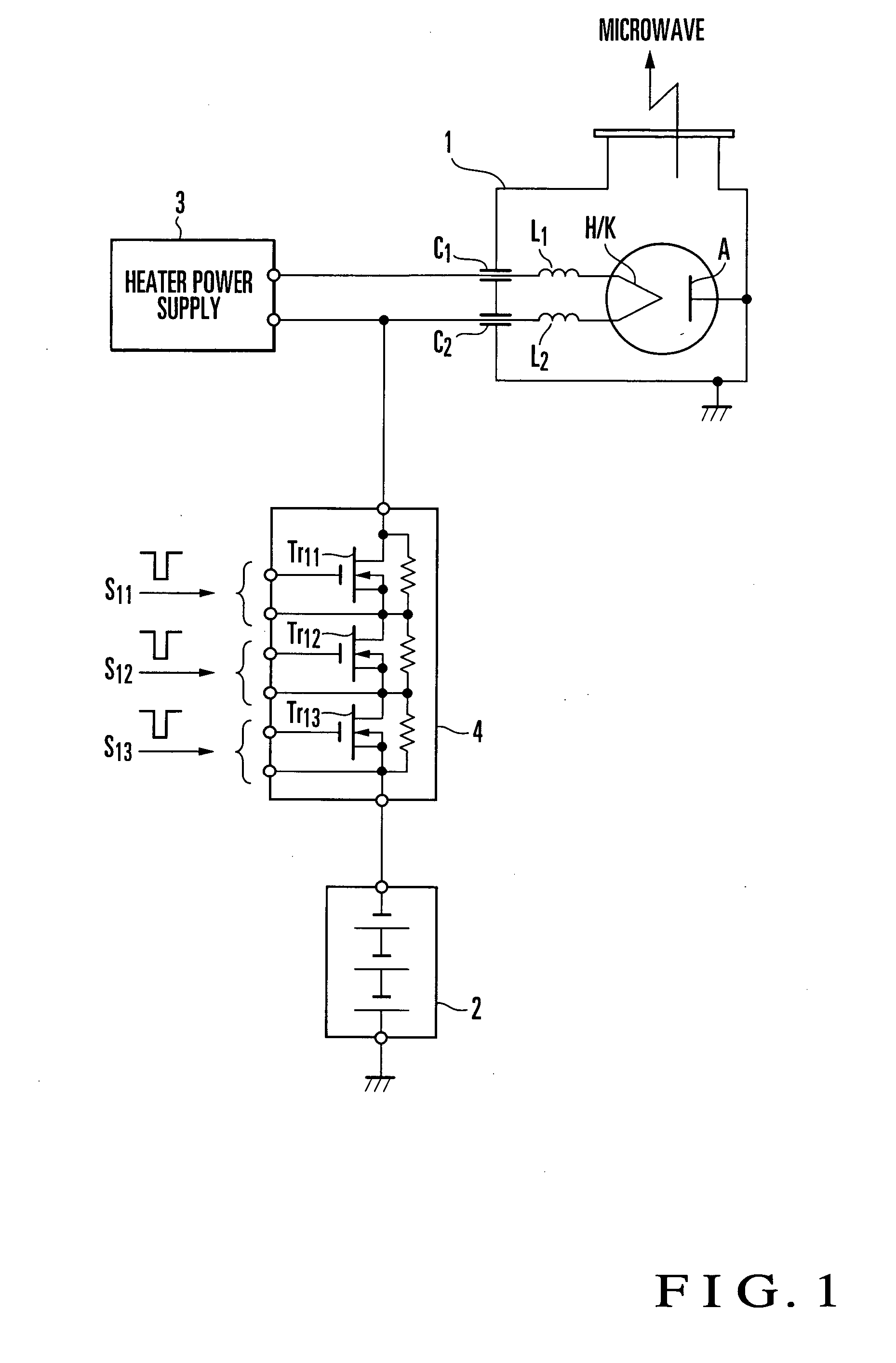
[0021]FIG. 1 shows the arrangement of a magnetron oscillating apparatus according to the first embodiment of the present invention. In the magnetron oscillating apparatus shown in FIG. 1, a switch circuit 4 is provided on the output side of an anode power supply (power supply unit) 2.
[0022] In the switch circuit 4, three switching elements Tr11, Tr12, and Tr13 are connected in series. The switching elements Tr11, Tr12, and Tr13 are turned on / off by the polarities of first input control signals S11, S12, and S13, respectively.
[0023] For example, when the switching elements Tr11, Tr12, and Tr13 are n-channel MOSFETs, they are turned on when the polarities of the control signals S11, S12, and S13 are positive with respect to the sources and off when the polarities are negative. When the switching elements Tr11 to Tr13 of the switch circuit 4 are ON, a negative voltage from the anode power supply 2 is output to a heater / cathode H / K. When the switching elements Tr11 to Tr13 are OFF, th...
second embodiment
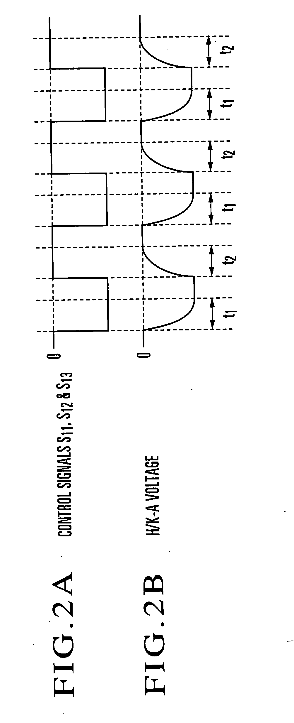
[0028] In the magnetron oscillating apparatus according to the first embodiment, a time constant is present which is the product of the resistance component of the output impedance of the anode power supply 2 viewed from the magnetron 1 and the capacitance value of the capacitors C1 and C2. This time constant has a great influence on the rise time and fall time of the voltage applied from the anode power supply 2 between the heater / cathode H / K and the anode A. Even when a pulse waveform as shown in FIG. 2A is used as the control signals S11, S12, and S13, the anode voltage rises and falls with a delay, and the waveform shown in FIG. 2B is obtained. For example, when the resistance component of the output impedance of the anode power supply 2 is about 7 kΩ, and the capacitance value of the capacitors C1 and C2 is about 2,000 pF, a rise time t1 and fall time t2 of the voltage become about 20 to 50 μs. The magnetron 1 oscillates by the voltage applied between the heater / cathode H / K and...
third embodiment
[0039] As described above, in the magnetron oscillating apparatus according to the first embodiment, falling of the microwave output from the magnetron 1 delays. As a result, since no steep pulse fall waveform is formed, the production efficiency of plasma afterglow which has an important function in the plasma processing decreases.
[0040] In the third embodiment, a magnetron oscillating apparatus having a discharge circuit to make the microwave quickly fall will be described.
[0041]FIG. 4 shows the arrangement of a magnetron oscillating apparatus according to this embodiment. The same reference numerals as in FIG. 1 denote the same or corresponding constituent elements in FIG. 4, and a description thereof will appropriately be omitted.
[0042] The magnetron oscillating apparatus shown in FIG. 4 has a discharge circuit 6 which removes charges stored in capacitors C1 and C2 when the applied voltage to a magnetron 1 is stopped. An anode power supply 20 is used in place of the anode pow...
PUM
 Abstract
Description
Claims
Application Information