
Magnetic head with domain stabilization and magnetic recording/reproducing apparatus using the same

a technology of magnetic recording head and domain stabilization, which is applied in the direction of magnetic recording head, data recording, instruments, etc., can solve the problems of insufficient stability for optimizing output, inability to overcome phenomena by conventional techniques, and disturbance of the linear output of the magnetoresistive sensor with respect to the magnetic field to be perceived, etc., to achieve high output and stability, narrow track width, and high recording density

Inactive Publication Date: 2005-10-13
HITACHI GLOBAL STORAGE TECH NETHERLANDS BV
View PDF19 Cites 9 Cited by
  • Summary
  • Abstract
  • Description
  • Claims
  • Application Information

AI Technical Summary

Benefits of technology

[0017] Under such circumstances, it is a feature of the present invention to provide a spin-valve type magnetic head that has an in-stack type domain control structure and can reconcile both high output and stable operation corresponding to higher recording density.
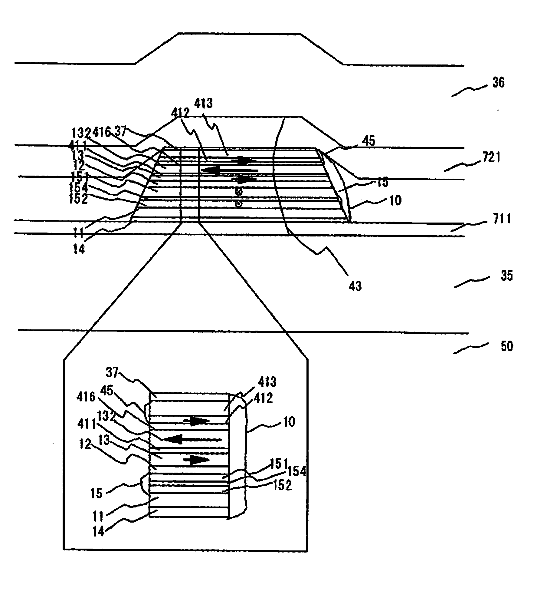
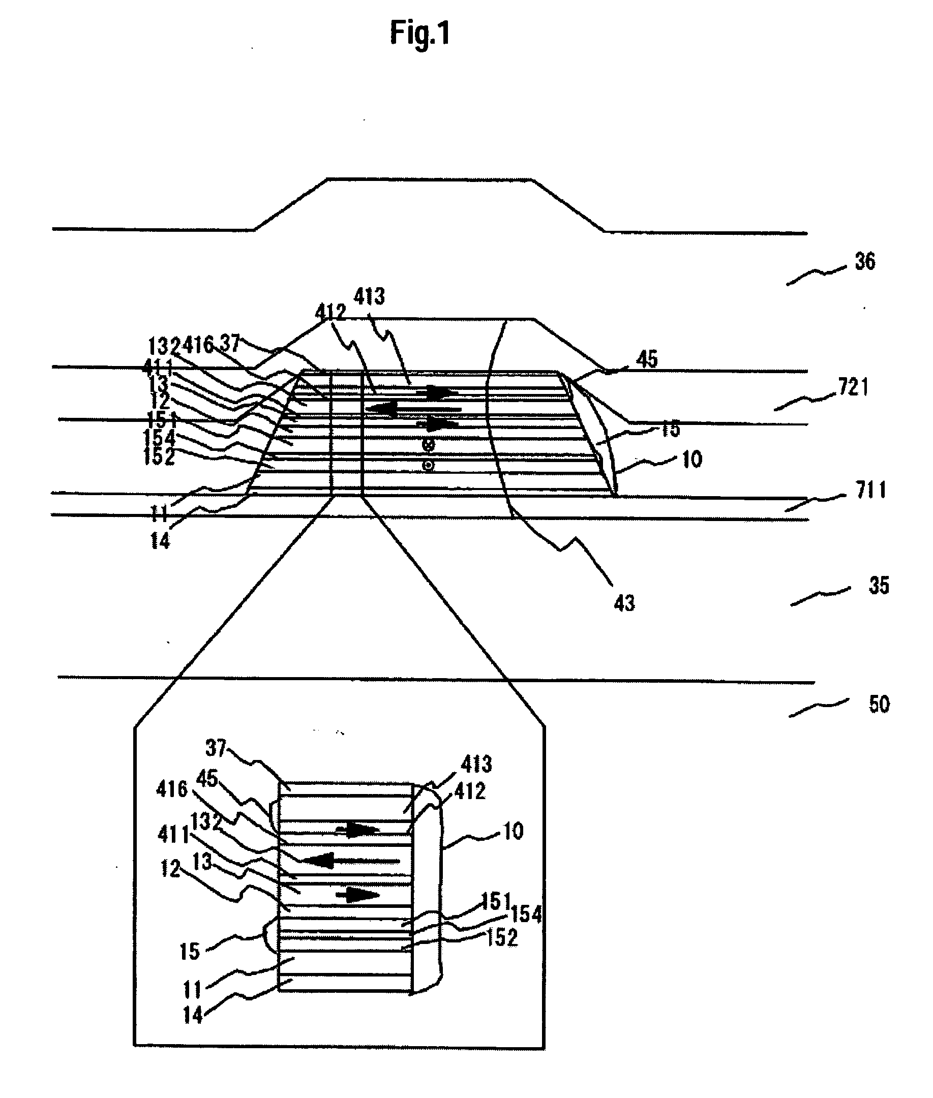
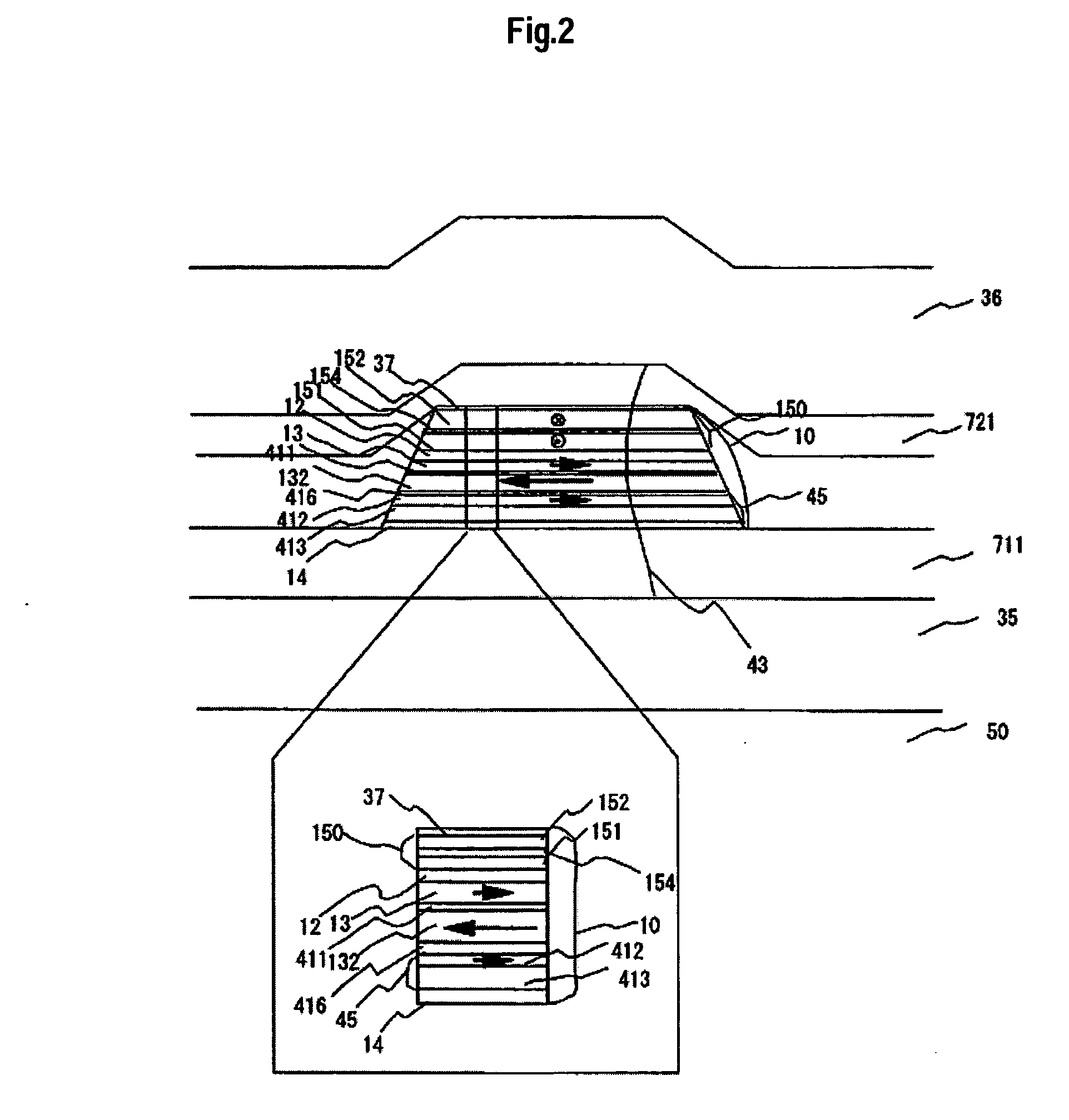
[0022] Because of the above described composition of the anti-parallel coupling layer and the weak anti-parallel coupling layer, when the magnetic field value is zero, the in-stack type domain control structure according to the present invention, that is, the three adjacent magnetic layers that are a domain-stabilization ferromagnetic layer, a soft anti-parallel layer, and a soft magnetic free layer can be magnetized in anti-parallel to each another like right / left / right. Consequently, each of the domain-stabilization ferromagnetic layer, the soft anti-parallel layer, and the soft magnetic free layer can have a double closed flux path structure, thereby the stability of the magnetic sensor is improved.
[0023] One feature of the present invention is to increase the number of sensors of a magnetic layer in which a closed flux path is formed for stable domain control from 2 to 3 or more so that domain control is realized with double or triple closed flux paths to control the balance among magnetization amounts more accurately. The domain-stabilization ferromagnetic layer, the non-magnetic isolated layer (anti-parallel coupling layer / weak anti-parallel coupling layer), and the soft magnetic free layer are formed almost in the same track width and self-aligned at their ends while the domain-stabilization ferromagnetic layer can generate a magnetic charge effectively in the track width direction due to the residual magnetization so that the soft magnetic free layer and the soft magnetic anti-parallel layer can cancel the magnetic charges each other at their ends to enable such single domain-stabilization. In other words, the domain-stabilization ferromagnetic layer and the soft magnetic free layer are composed so as to cancel the magnetic charges mutually at the end of the soft magnetic anti-parallel layer. In other words, the domain-stabilization ferromagnetic layer and the soft magnetic free layer are composed so that the total of the magnetic amounts of the domain-stabilization ferromagnetic layer and the soft magnetic free layer (the total of the products of the magnetic flux density and the film thickness) becomes approximately the same as the magnetic amount of the soft anti-parallel layer. This is because the domain-stabilization ferromagnetic layer and the soft magnetic anti-parallel layer, as well as the ferromagnetic free layer and the soft magnetic anti-parallel layer, are magnetized in anti-parallel to each other respectively when the magnetic field value is around zero. It is also possible to set the total of the magnetization amounts of the domain-stabilization ferromagnetic layer and the soft magnetic free layer larger than the magnetization amount of the soft magnetic anti-parallel layer only slightly (about 20%) with expectation of a slight loss of the magnetic charge at the end. Because the domain control structure is assumed as described above, the present invention can obtain the above single domain-stabilization effect stably without using any other domain control structure, such as a hard bias structure.
[0027] On the contrary, the weak anti-parallel coupling layer of the present invention should be weaker in effect than the above anti-parallel coupling layer. Concretely, any of such materials as Ru, Ir, Os, Re, Rh, etc., that are all favorable materials for the above anti-parallel coupling layer is alloyed with another to dilute the material or laminated with another extremely thin material to realize predetermined weak anti-parallel coupling. Another material described above may be any of the following general materials such as Cu, Ta, etc., to save the cost.
[0029] As described above, the present invention employs a double closed flux path structure in which three magnetic layers of a soft magnetic anti-parallel layer, a soft magnetic free layer, and a domain-stabilization ferromagnetic layer can cancel their edge magnetization each other. This is why the present invention can realize a magnetoresistive magnetic sensor that reconciles both of high output and stability. As such, this sensor can be used as a read head in a magnetic recording / reproducing apparatus to realize high recording density, that is, recording in a shorter wavelength and in a narrower track width on the subject recording medium, thereby obtaining a sufficient read output and keeping the recording in a desired state.

Problems solved by technology

However, a problem arises in the single domain-stabilization realized by the above in-stack type domain control structure.
When the track of the magnetoresistive sensor is narrowed, more specifically when the track width becomes 0.1 μm or smaller, the influence of the demagnetizing field at the ends of the magnetic film surpasses the single domain-stabilization effect, thereby disturbing the linear output of the magnetoresistive sensor with respect to the magnetic field to be perceived.
In that case, however, the track is narrowed in width; whereby the stability comes to be insufficient for optimizing outputs.
This phenomenon cannot be overcome by any conventional technique having been disclosed as in-stack type domain control techniques.
This is why it is impossible to reconcile the stabilization realized by thinning the domain-stabilization ferromagnetic layer and keeping the large magnetoresistive output with the use of a free layer having a predetermined thickness.
The domain control structure and the magnetoresistive layered film of prior techniques have not realized such a stable structure for magnetic heads having a narrower track width respectively in recent years.

Method used


Image

  • Magnetic head with domain stabilization and magnetic recording/reproducing apparatus using the same
  • Magnetic head with domain stabilization and magnetic recording/reproducing apparatus using the same
  • Magnetic head with domain stabilization and magnetic recording/reproducing apparatus using the same

Examples


Embodiment Construction

[0047] Hereunder, the examples of the present invention will be described with reference to the accompanying drawings. To make it easier to understand, the same numerals / symbols will be used for the same functional items in those drawings.

[0048] A thin film of a giant magnetoresistive layered film according to an embodiment of the present invention is formed as follows with the use of a radio-frequency magnetron sputtering apparatus. The following materials are layered on a ceramic substrate sequentially in an atmosphere of 1 to 6 mTorr of argon. As sputtering targets, tantalum, a nickel-20 at % iron alloy, copper, cobalt, MnPt, ruthenium, alumina, magnetite, and MnIr are used. At first, on a Co target is disposed 1 cm square Fe chips as needed to adjust the composition. On the Co target is disposed Pt chips to form a CoPt film. A layered film is formed by applying a high frequency power to each cathode on which a target is disposed to generate plasma in the apparatus beforehand, t...


PUM


Abstract

Embodiments of the invention provide a spin-valve type magnetic head that satisfies the requirements of both high read output and stability with narrow tracks. In one embodiment, a domain control film is formed on a magnetoresistive layered film in the same track width. A double closed flux path structure that uses three magnetic layers is employed with magnetic coupled structure in both ends of the track. The three magnetic layers are a soft magnetic free layer, a domain-stabilization ferromagnetic layer, and a soft magnetic anti-parallel layer.

Description

CROSS-REFERENCES TO RELATED APPLICATIONS [0001] This application claims priority from Japanese patent application No. JP 2004-115773, filed Apr. 9, 2004, the entire disclosure of which is incorporated herein by reference. BACKGROUND OF THE INVENTION [0002] The present invention relates to a magnetic head and a recording / reproducing apparatus that uses the same, more particularly to a magnetic head including a magnetoresistive sensor and a magnetic recording / reproducing apparatus that uses the same. [0003] The high recording density magnetic recording technique that mainly handles hard disk drives uses such a magnetoresistive head as a read sensor. The read sensor depends significantly on the performance of the magnetic recording technique. While the recording density of magnetic recording / reproducing apparatuses has been improved rapidly, none of the prior techniques has realized a magnetoresistive head having both sensitivity and output with good symmetric performance for external ...

Claims


Application Information

Patent Timeline
IPC IPC(8): G11B5/127G11B5/33G11B5/39H01L43/08
CPCB82Y10/00G11B5/3932G11B5/3903
Inventor HOSHIYA, HIROYUKIHOSHINO, KATSUMIHATATANI, MASAHIKOMEGURO, KENICHI
Owner HITACHI GLOBAL STORAGE TECH NETHERLANDS BV
Learn More