Image processing device and method

a technology of image processing and image, applied in the field of image processing apparatus and a method, can solve the problems of reducing the luminance variation of the image as a whole, the range of supportable luminance grayscales the apparatus is not yet widened, so as to achieve the effect of reducing the load of calculation, small memory capacity consumption, and easy hardware construction

Inactive Publication Date: 2005-10-13
SONY CORP
View PDF9 Cites 83 Cited by
  • Summary
  • Abstract
  • Description
  • Claims
  • Application Information

AI Technical Summary

Benefits of technology

[0024] The present invention is conceived in view of the aforementioned situation, and an object thereof is to realize a grayscale compression technique which requires only a small memory capacity to be consumed and a less load of calculation, allows easy hardware construction, and ensures a large grayscale compression effect.

Problems solved by technology

On the other hand, display apparatuses for displaying moving image and still image such as CRT (Cathode Ray Tube) and LCD (Liquid Crystal Display), projection apparatuses such as projector, and various printing apparatuses are not yet widened in their supportable dynamic range of pixel values at present, and have only a limited range of supportable luminance grayscale.
However, as described in the above, a uniform re-assignment of the grayscale of pixel values of the wide-DR image simply to the narrow dynamic-range only results in a reduced luminance variation of the image as a whole, and consequently in conversion into a poorly-looking image with a degraded contrast.
It is, however, difficult to obtain a satisfactory result in every circumference only by an effort based on the grayscale assignment.
In an exemplary case where an image has a plurality of principal subjects and has a background with a uniform luminance and a relatively wide area (e.g., blue sky), the subjects often fail in obtaining a sufficient grayscale assigned thereto.
The high-frequency filter is, however, causative of overshoot at the contour portion of the subject and of noise emphasis at the flat portion, and is therefore understood as being not capable of always ensuring desirable images.
The third grayscale conversion technique, however, still suffers from a problem of overshoot at the contour portion of the subject, and noise emphasis at the flat portion similarly to the second grayscale conversion technique, so that there is also proposed a method of solving the problem by using a non-linear filter (e.g., median filter) in the process of division into the low-frequency-component image and high-frequency-component image.
The former results in an unnatural image having only the high-frequency component thereof enhanced, and is far from successful in obtaining effective grayscale compression results.
The latter, however, suffers from a problem in that the process therefor needs a large-capacity memory mainly for the delay line or frame memory, so that it is not adaptive to hardware construction.
This sort of grayscale compression technique has, however, not been proposed yet.
Additional problems, as described below, commonly reside in the above-described first to third grayscale compression techniques.
A first problem relates to generation of overshoot in the luminance at the contour portion of the subject in parallel with emphasis of the high-frequency components.
The two-dimensional, non-linear filter of this size expected as being realized on the software basis, however, raises a problem in that cost for the calculation will grow extremely high, and that expected as being realized on the hardware basis raises a problem in that the circuit scale will grow large due to necessity of a large volume of delay lines.
A second problem relates to control of the amount of contrast emphasis of high-frequency components in the high-luminance region and low-luminance region.
The emphasis of the high-frequency component, however, results in clipping of the luminance at around the maximum luminance and minimum luminance acceptable by a display apparatus or the like, and consequently in loss of detail of the image, so that the grayscale conversion could not be said as being appropriate, and this raises a need for some countermeasure by which the clipping of luminance is avoidable.
Another problem resides in that an excessive emphasis of the contrast results in an image having an unnaturally enhanced contour portion of the subject, even under a condition not causative of clipping of the luminance.

Method used


Image

  • Image processing device and method
  • Image processing device and method
  • Image processing device and method

Examples


Embodiment Construction

[0107] A digital video camera as one embodiment of the present invention will be explained below referring to the attached drawings.

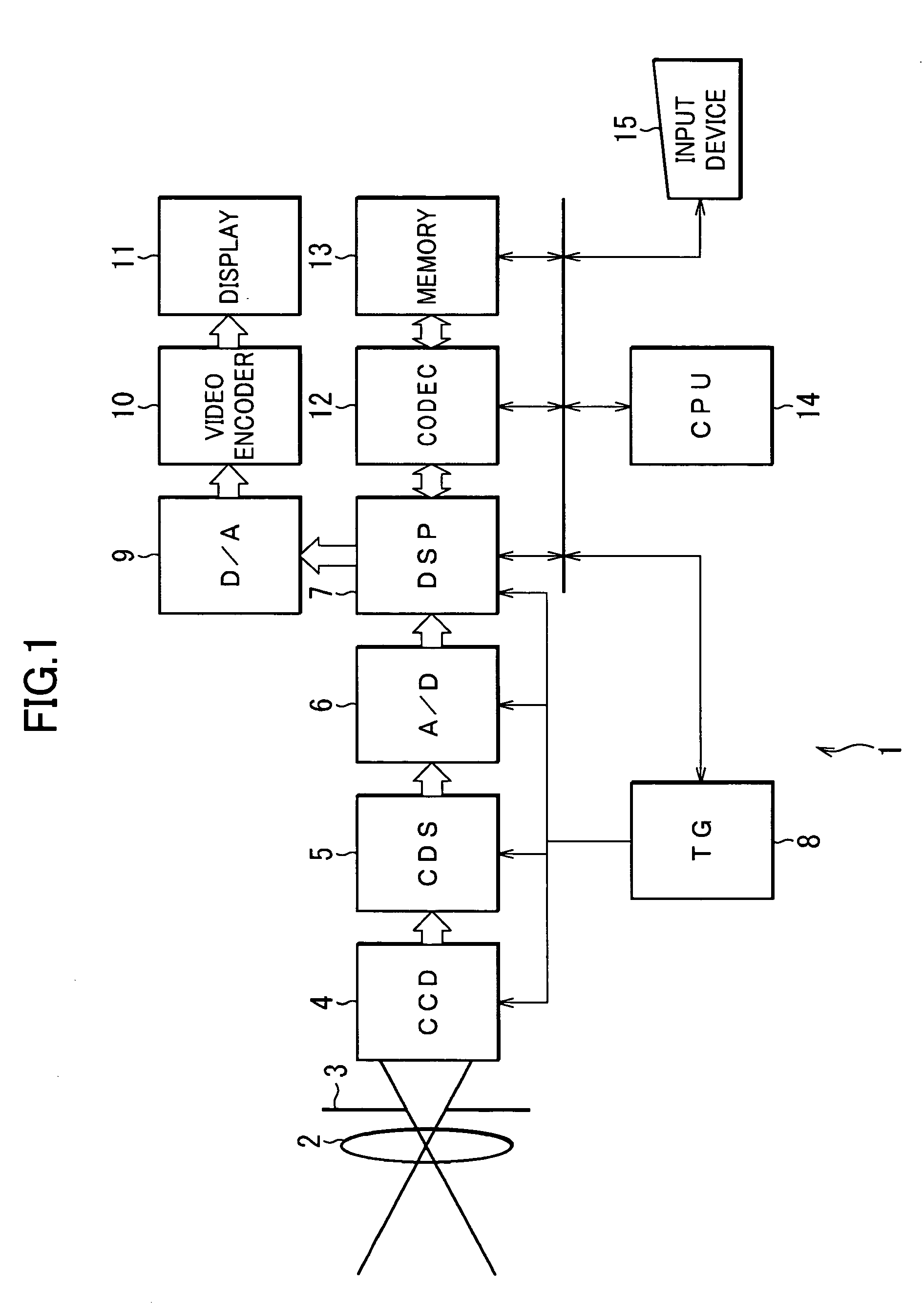
[0108]FIG. 1 shows an exemplary configuration of a digital video camera as one embodiment of the present invention. The digital video camera 1 takes a picture of a subject, generates a wide-DR image having a dynamic range of pixel values wider than a general one, saves the image into a predetermined storage medium, and outputs the wide-DR image after converting it into a narrow-DR image having a dynamic range of pixel values narrower than a general one, to a built-in display also used as a composition-determining finder or as an image monitor, or to external apparatuses.

[0109] The digital video camera 1 is roughly constructed from an optical system, a signal processing system, a recording system, a display system and a control system.

[0110] The optical system is constructed from a lens 2 for condensing a photo-image of a subject, a stop 3 for regulat...


PUM


Abstract

The present invention relates to an image processing apparatus and a method, and in particular to an image processing apparatus and a method preferably applicable to conversion of a wide dynamic-range image having a dynamic range of pixel values wider than the normal one to a narrow dynamic-range image having a narrower dynamic range of pixel values, and to enhancement of contrast. In step S1, an input wide-DR luminance image of the current frame is converted into a narrow-DR luminance image based on the intermediate information calculated for the previous frame's wide-DR luminance image. In step S2, the stored intermediate information of the previous frame is updated using the calculated intermediate information. In step S3, it is determined if there is any succeeding frame. If there is the succeeding frame, the process returns to step S1 and processes thereafter are repeated. The present invention is applicable to a digital video camera and the like.

Description

TECHNICAL FIELD [0001] The present invention relates to an image processing apparatus and a method, and in particular to an image processing apparatus and a method preferably applicable to conversion of a wide dynamic-range image having a dynamic range of pixel values wider than the normal one to a narrow dynamic-range image having a narrower dynamic range of pixel values, and to enhancement of contrast. BACKGROUND ART [0002] Conventionally, solid-state imaging elements such as CCD (Charge Coupled Device) and CMOS (Complementary Metal-Oxide Semiconductor) have been widely used for the imaging instruments such as video cameras and still cameras; and optical measurement apparatuses such as component inspection apparatus used in FA (Factory Automation) and optical measurement apparatuses such as electronic fiberscope used in ME (Medical Electronics). [0003] In recent years, there are proposed a large number of techniques for obtaining an image having a wide dynamic-range (referred to a...

Claims


Application Information

Patent Timeline
Patent Type & Authority Applications(United States)
IPC IPC(8): H04N1/393H04N1/407H04N5/20H04N9/68
CPCH04N1/3935H04N9/68H04N5/20H04N1/407H04N1/393
Inventor MITSUNAGA, TOMOO
Owner SONY CORP
Why Eureka
Try Eureka