
Polymer electrolyte fuel cell

a fuel cell and electrolyte technology, applied in the field of polymer electrolyte fuel cells, can solve the problems of difficult to obtain reliable properties, easy blockage (flooding) phenomenon of micropores of electrodes by condensation of water vapor, and serious environmental problems caused by fossil fuel consumption, so as to achieve the effect of restrainting the increase of activation over voltag

Inactive Publication Date: 2005-10-13
HONDA MOTOR CO LTD +1
View PDF3 Cites 50 Cited by
  • Summary
  • Abstract
  • Description
  • Claims
  • Application Information

AI Technical Summary

Benefits of technology

[0010] The present invention was completed in view of the above-mentioned circumstances, and an object of the invention is to provide a polymer electrolyte fuel cell having superior power generation efficiency under high voltage operation, particularly under low humidity operation.
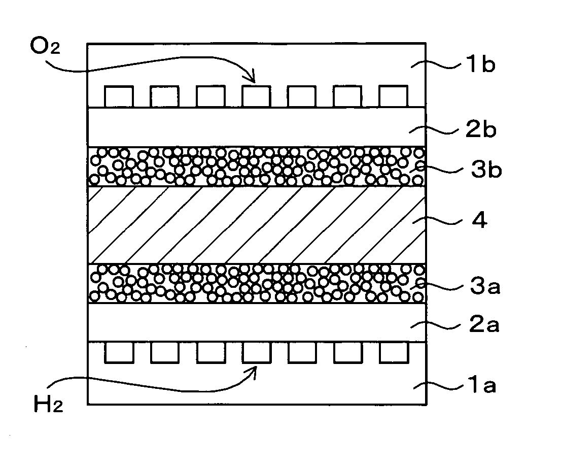
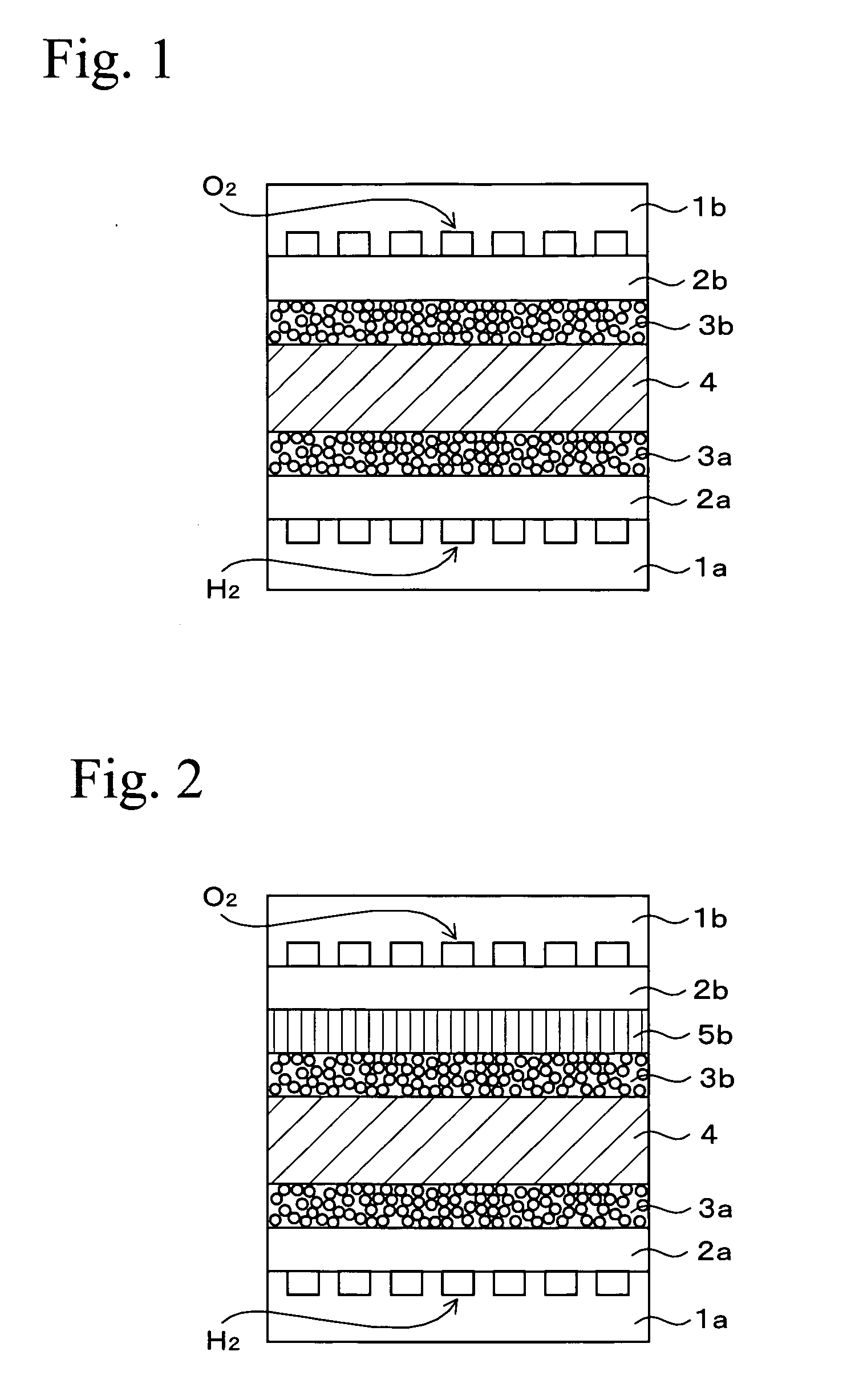
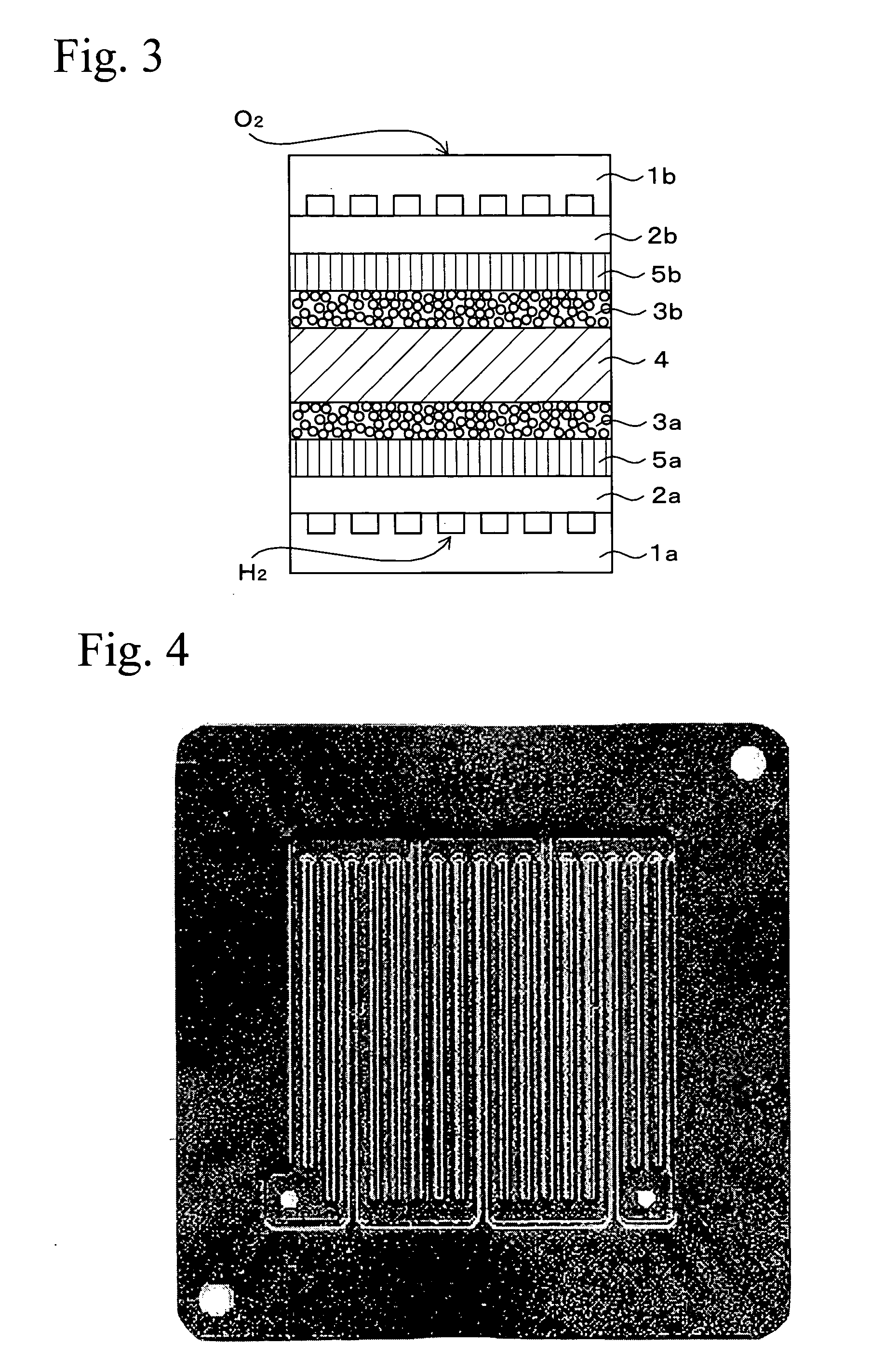
[0012] In such a polymer electrolyte fuel cell of the present invention, since the water holding layer having ion exchange resin, carbon particles, and vapor grown carbon fiber is arranged, water generated by the reaction is held in this water holding layer. Therefore, in the case in which water is in short supply in the catalytic layer under low humidity operation, water is supplied from the water holding layer, and as a result, increasing of activation over voltage can be restrained.

Problems solved by technology

Recently, exhaustion of petroleum resources is a crucial issue, and environmental problems such as air pollution and global warming caused by consumption of fossil fuels have become serious.
Therefore, in a high-voltage operation, water is generated faster than water vapor at the cathode can be exhausted, and as a result, a blockage (flooding) phenomenon of micropores of the electrode by condensation of water vapor may easily occur.
If the flooding phenomenon occurs, the number of reaction sites is reduced, the reaction cannot be promoted efficiently, and it would be difficult to obtain reliable properties for a long period.
However, the number of functional groups on the surface of the supporting body and specific surface area are reduced by a heat treatment of graphitization, and as a result, the water holding property of graphite in the electrode is deteriorated.
Therefore, under a low humidity operation, i.e., not more than 50% humidity, required water is in short supply, an activation over voltage of catalytic reaction is increased, and power generation efficiency is deteriorated.

Method used


Image

  • Polymer electrolyte fuel cell
  • Polymer electrolyte fuel cell
  • Polymer electrolyte fuel cell

Examples


example 1

[0037] Carbon black (trade name: Ketjen black EC, produced by Cabot) was graphitized by a heat treatment at 2800° C. Platinum was put on the carbon black so that there was a 50:50 of weight ratio of carbon black and platinum, to prepare a graphitized support catalyst. 10 g of this graphitized support catalyst, 35 g of ion conductive polymer solution (trade name: Nafion DE2020), and 1.84 g of crystalline carbon fiber (VGCF, produced by Showa Denko) were mixed to prepare a cathode catalyst paste. This catalyst paste was coated on a FEP sheet so that there was 0.3 mg / cm2 of Pt, and this was dried to prepare electrode sheet A.

[0038] 36.8 g of ion conductive polymer solution (Nafion SE20192) and 10 g of Pt—Ru supporting carbon particle (trade name: TEC61E54, produced by Tanaka Kikinzoku Kogyo) were mixed to prepare an anode catalyst paste. This catalyst paste was coated on a FEP sheet so that there was 0.15 mg / cm2 of Pt, and this was dried to prepare electrode sheet B.

[0039] The electr...

example 2

[0047] Except for using sulfonated polyarylene membrane as the electrolyte membrane instead of Nafion 112, MEA of Example 2 was prepared as similar to Example 1. This polyarylene membrane was produced by following processes (1) to (6).

(1) Preparation of 4-[4-(2,5-dichlorobenzoyl)phenoxy]benzene sulfonic acid sodium salt (A-SO3Na)

[0048] 2,5-dichloro-4′-phenoxybenzophenone (A, 137.3 g, 400 mmol) was put in a 3 L three-necked flask equipped with a stirring device and cooling tube, and 500 mL of 1,2-dichloroethane (1,2-DCE) was added and dissolved. Furthermore, 2 M of acetyl sulfuric acid solution prepared by mixing 56 mL of concentrated sulfuric acid, 152 mL of acetic anhydride, and 400 mL of 1,2-DCE, was added to the flask while stirring, and the reaction was performed in an oil bath at 60° C. After the predetermined period, 300 mL of 1-propanol was added to stop the reaction. Next, the reaction liquid was concentrated to a volume of 400 mL, and NaOH aqueous solution (120 g (3 mol) / ...

example 3

[0058] A test unit was prepared by arranging a metallic separator on both sides of the MEA of Example 1.


PUM

PropertyMeasurementUnit
specific surface areaaaaaaaaaaa
lattice spaceaaaaaaaaaa
humidityaaaaaaaaaa

Abstract

A polymer electrolyte fuel cell consists of plural units, and the unit has an anode side separator, an anode diffusion layer, an anode catalytic layer, polymer electrolyte membrane, a cathode catalytic layer, a cathode diffusion layer, and a cathode side separator. The cathode catalytic layer further includes a catalyst in which platinum or platinum alloy is supported on a carbon supporting body having an average lattice space d002 of [002] surface of 0.338 to 0.355 nm and specific surface area of the supporting body of 80 to 250 m2 / g, electrolyte containing ion exchange resin, and vapor grown carbon fiber. Furthermore, a water holding layer containing ion exchange resin, carbon particles, and vapor grown carbon fiber is arranged at an interface of the cathode diffusion layer and the cathode catalytic layer.

Description

BACKGROUND OF THE INVENTION [0001] 1. Technical Field [0002] The present invention relates to a polymer electrolyte fuel cell, and in particular, relates to a technique for improving power generation efficiency in high-voltage operation. [0003] 2. Background Art [0004] Recently, exhaustion of petroleum resources is a crucial issue, and environmental problems such as air pollution and global warming caused by consumption of fossil fuels have become serious. Under these circumstances, fuel cells have attracted much attention as a clean power source for electric motors in which carbon dioxide is not generated, and such fuel cells are being widely developed and used. [0005] In the case in which such a fuel cell is used in a vehicle, a polymer electrolyte fuel cell in which a polymer electrolyte membrane is used is desirably used since high voltage and large current can be obtained. A membrane electrode assembly for the polymer electrolyte fuel cell is produced as follows: a catalyst suc...

Claims


Application Information

Patent Timeline
Patent Type & Authority Applications(United States)
IPC IPC(8): H01M4/86B01D71/52B01D71/82H01M4/92H01M4/94H01M4/96H01M8/02H01M8/04H01M8/10
CPCB01D71/52Y02E60/521H01M4/921H01M4/926H01M8/0234H01M8/0239H01M8/0243H01M8/04291H01M8/1004H01M8/1025H01M8/1027H01M8/103H01M8/1032H01M8/1039H01M2300/0082B01D71/82Y02E60/50H01M8/141B01D71/522
Inventor FUKUDA, KAORUEGUCHI, TAKUTSUJI, MAKOTO
Owner HONDA MOTOR CO LTD
Learn More