Apparatus for enhancing combustion efficiency of liquid fuel

a technology of liquid fuel combustion efficiency and apparatus, which is applied in the direction of combustion air/fuel air treatment, machines/engines, lighting and heating apparatus, etc., can solve the problems of reducing the efficiency of removing nox is lowered, and it is not possible to stably remove unburned matter such as co and hc, etc., to achieve the effect of reducing the amount of unburned matter, no maintenance cos

Active Publication Date: 2005-11-03
HASHIMOTO KENICHI
View PDF4 Cites 13 Cited by
  • Summary
  • Abstract
  • Description
  • Claims
  • Application Information

AI Technical Summary

Benefits of technology

[0023] Since the high combustion efficiency device for liquid fuel according to the present invention has the structure as described above, almost no maintenance cost is required, combustion efficiency of liquid fuel in an engine portion is improved, the amount of unburned matters is reduced as much as possible, and generation of nitrogen oxide is suppressed.
[0024] Further, if the surface of the hollow member is covered by the far-infrared ray generating substance such as hard alumite, the hollow member is used i

Problems solved by technology

However, the catalysts are degraded due to use for a long period of time, and thus, the efficiency for removing the unburned matters such as CO and HC, and NOx is lowered.
Therefore, it is not poss

Method used


Image

  • Apparatus for enhancing combustion efficiency of liquid fuel
  • Apparatus for enhancing combustion efficiency of liquid fuel
  • Apparatus for enhancing combustion efficiency of liquid fuel

Examples


first example

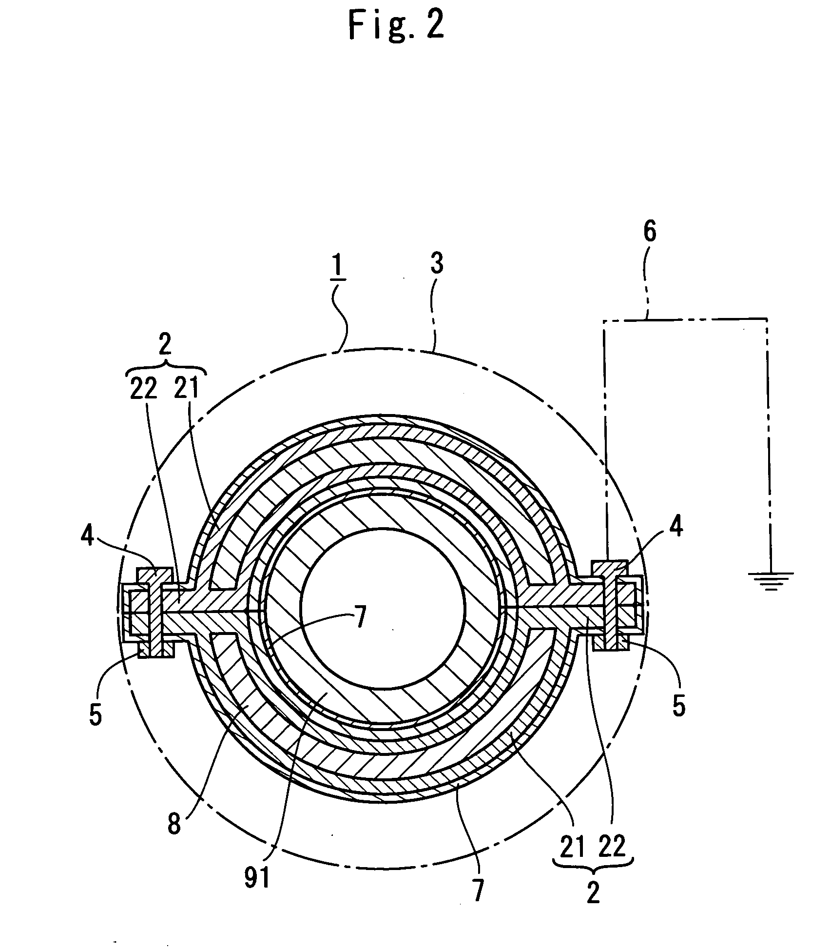
[0086] A surface of an aluminum tube having a diameter of 6 mm and a thickness of 0.5 mm was subjected to an anodic oxidation process to form a hard alumite layer having a thickness of 30 μm as a far-infrared ray generating substance.

[0087] Then, an electrically conductive solution which is obtained by dispersing and mixing tourmaline particles and carbon graphite particles by 10 weight %, respectively, was filled in the aluminum tube covered by hard alumite. Both ends of the tube were closed to obtain a high combustion efficiency tube having a length of 100 mm.

[0088] Ends of nine high combustion efficiency tubes as obtained above were connected by a lead wire so that electricity flows through the hollow member. In this manner, the high combustion efficiency device body was obtained.

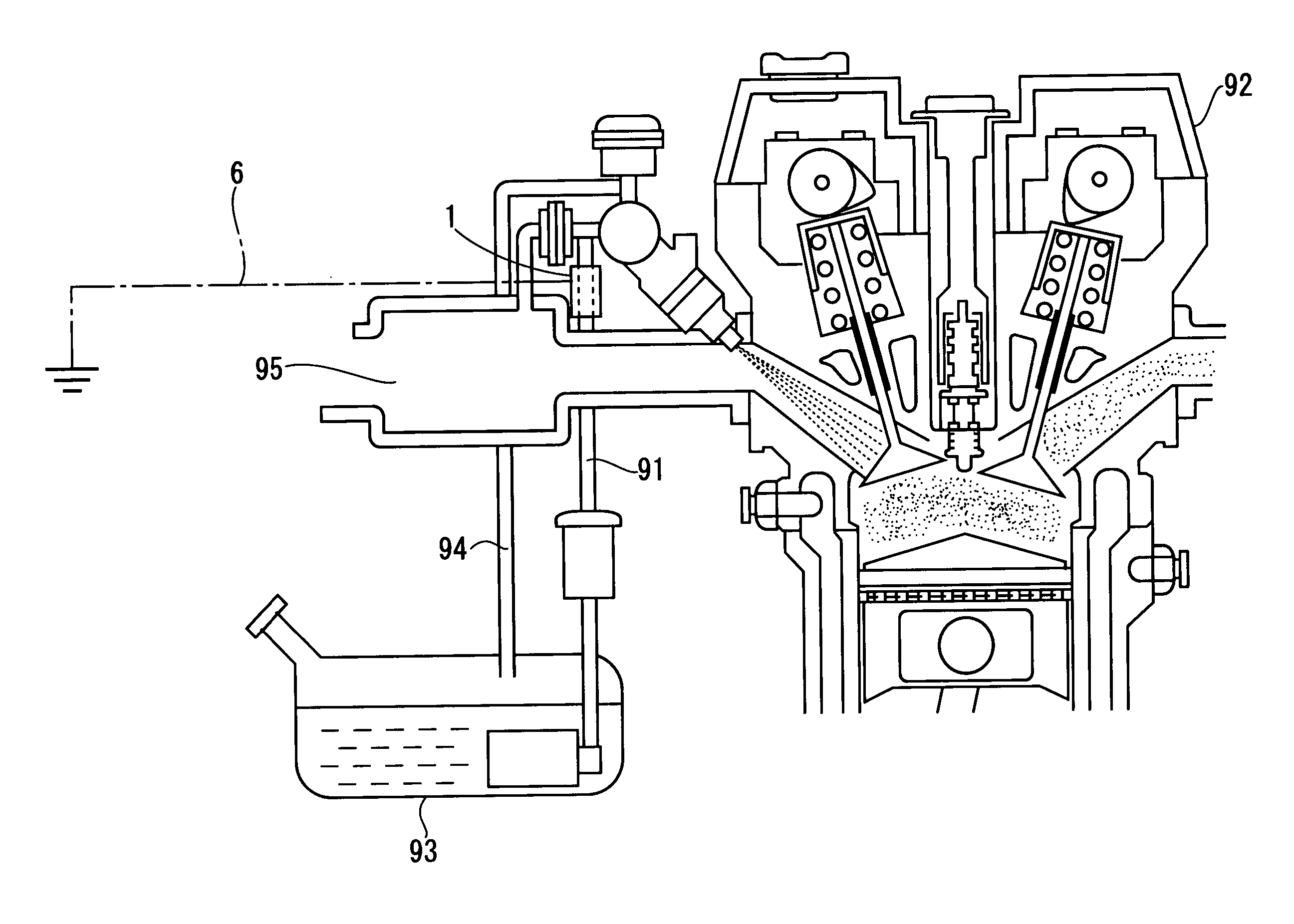
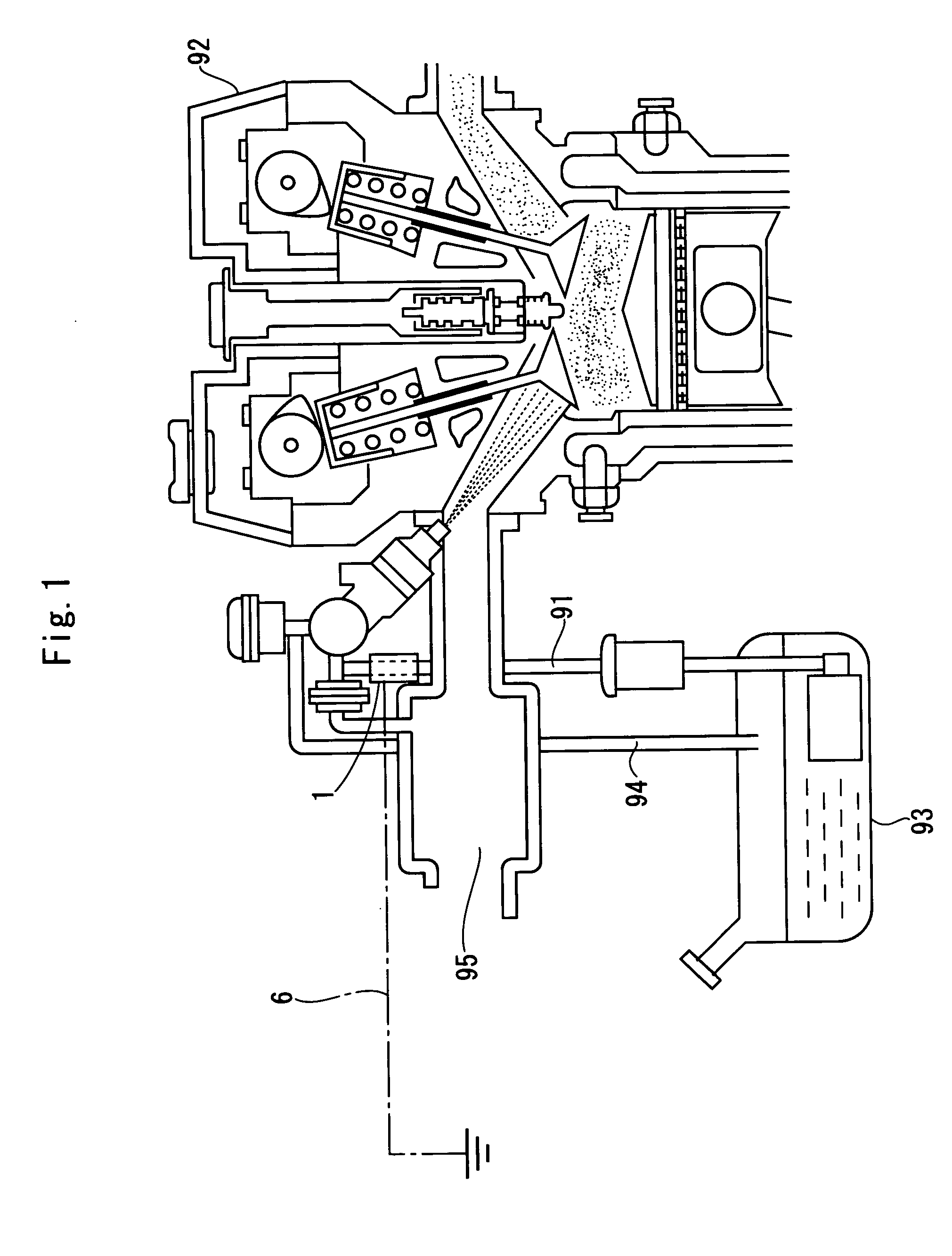
[0089] The high combustion efficiency device body was used for Rafaga produced by Honda Motor Co., Ltd. The high combustion efficiency device was wound around a fuel pipe as a fuel passage such that t...

second example

[0091] The Second Example was carried out in the same manner as with the First Example except that the high combustion efficiency device is attached to the fuel pipe of a Step Wagon produced by Honda Motor Co., Ltd. The engine was started, and when the engine sound was stabilized, CO, CO2, O2, HC, and NOx in the exhaust gas at the time of idling (730 rpm) and at the time of idling away of the engine were measured using the gas concentration measurement device (Dicom 4000 produced by AVL Corporation). The results are shown in a Table 2 together with measurement results in the case in which the high combustion efficiency device is not mounted.

[0092] As can be seen from the Tables 1 and 2, with the use of the high combustion efficiency device according to the present invention, the amounts of CO and HC in the exhaust gas are significantly reduced, and the combustion efficiency is improved in comparison to the case in which the high combustion efficiency device is not used. Further, as...

third example

[0093] Four high combustion efficiency devices used in the First Example were placed in 15 liters of unprocessed gasoline in a polytank. The gasoline was stirred, and left for five minutes to obtain the processed gasoline.

[0094] The specific gravity of the obtained processed gasoline and the specific gravity of the unprocessed gasoline were measured. The processed gasoline and the unprocessed gasoline were individually filled in a fuel tank of a Step Wagon produced by Honda Motors Co., Ltd. The high combustion efficiency device according to the present invention is not mounted on the Step Wagon. In each of the cases, the engine was started, and CO, CO2, O2, HC, and NOx in the exhaust gas at the time of idling (730 rpm) and at the time of idling away of the engine were measured using the gas concentration measurement device (Dicom 4000 produced by AVL Corporation). The results are shown in a table 3.

[0095] As can be seen from Table 3, when the high combustion efficiency device acco...


PUM


Abstract

A high combustion efficiency device for liquid fuel comprises a hollow member made of electrically conductive material, liquid filling the hollow member and tourmaline particles dispersed in the liquid, wherein the high combustion efficiency device is formed to be attachable to at least part of a fuel tank of liquid fuel and a fuel passage extending from the fuel tank to a combustion device of the liquid fuel.

Description

TECHNICAL FIELD [0001] The present invention relates to a high combustion efficiency device for liquid fuel. BACKGROUND ART [0002] The exhaust gas from automobiles contains environmental pollutants including unburned matters such as CO (carbon monoxide) and HC (hydrocarbon), and NOx (nitrogen oxide), or the like. [0003] In an automobile, as disclosed in Japanese Unexamined Patent Application No. Hei-7-174017, catalysts for removing unburned matters such as CO and HC, and NOx are provided in an exhaust gas conduit for preventing the unburned matters such as CO and HC, and NOx from being discharged into the atmospheric air. [0004] However, the catalysts are degraded due to use for a long period of time, and thus, the efficiency for removing the unburned matters such as CO and HC, and NOx is lowered. Therefore, it is not possible to stably remove the unburned matters such as CO and HC, and NOx. Further, since the degraded catalysts need to be replaced periodically, maintenance cost for...

Claims


Application Information

Patent Timeline
IPC IPC(8): C10G32/02F02M27/04F02M27/06F02M27/08F23K5/08
CPCC10G32/02F02M27/04F02M27/045F23K2301/101F02M27/08F23K5/08F02M27/06F23K2300/101
Inventor HASHIMOTO, KENICHINAKAGAWA, HIROFUMI
Owner HASHIMOTO KENICHI
Why Eureka
Try Eureka