Method and apparatus for microcellular polymer extrusion

a microcellular polymer and extrusion method technology, applied in the field of polymer foam processing, can solve the problems of non-uniform distribution of cells in the material, low number of voids or cells per unit volume of material, and inability to achieve thin sheets and sheets with very smooth finishes. to achieve the effect of constant pressur

Inactive Publication Date: 2005-11-17
TREXEL
View PDF68 Cites 46 Cited by
  • Summary
  • Abstract
  • Description
  • Claims
  • Application Information

AI Technical Summary

Benefits of technology

[0020] In another aspect, the invention provides a method that involves maintaining in extrusion apparatus a relatively constant pressure profile in a mixture of fluid polymeric material and fluid that is a gas under ambient conditions and that can serve as a blowing agent. Specifically, the method involves providing an extruder having an inlet at an inlet end thereof designed to receive a precursor of foamed material and an outlet at an outlet end thereof designed to release foamed material from the extruder and an enclosed passageway connecting the inlet with the outlet constructed and arranged to advance a fluid polymeric stream within the passageway in a downstream direction from the inlet end toward the outlet end. The method involves establishing a stream of fluid polymeric material flowing in the extruder in a downstream direction and introducing a fluid that is a gas under ambient conditions into the stream at an injection location of the extruder. The stream is maintained, downstream of the injection location and upstream of a foaming region, under pressure varying by no more than about 1,500 psi. The extruder can include a nucleation region at which a single-phase solution of fluid polymeric material and blowing agent flowing therethrough is nucleated, and the relatively constant pressure can be maintained downstream of the injection location and upstream of the nucleation region. The fluid that is gas under ambient conditions, and that can serve as blowing agent, can be introduced into the extruder through one or more orifices, for example 4, 25, 50 or 100 or more orifices, and can be introduced therethrough simultaneously. Introduction of the gas can be carried out in an extruder barrel with a screw including flights passing each of the orifices at a rate of at least about 0.5 passes per second, or more.

Problems solved by technology

Under other, typically more violent foaming conditions, the cells rupture or become interconnected and an open-cell material results.
The number of voids or cells per unit volume of material typically is relatively low according to that technique and often the material exhibits a non-uniform distribution of cells throughout the material.
Therefore, thin sheets and sheets having very smooth finishes typically cannot be made by the technique, and materials produced typically have relatively low mechanical strengths and toughness.
The technique is designed to form a high-density skin layer on the foamed material since, according to Hayashi, et al., with single-hole dies the extrudate is deformed by foaming after the material leaves the die and it is not possible to form a skin layer uniformly.
The stream is rapidly heated, and the resulting thermodynamic instability (solubility change) creates sites of nucleation, while the system is maintained under pressure preventing significant growth of cells.
While conventional foam processing can operate at very high output rates, typical known continuous microcellular extrusion production rates do not approach the rates achievable with conventional processes.
However, extruding very thin material or very thick microcellular material can be difficult.
With respect to thick sheets, it has been difficult or impossible to create the necessary solubility change uniformly throughout a thick product produced by extrusion to produce a thick microcellular article continuously.
Additional control problems exist in many known thin foam sheet extrusion techniques.
Accordingly, it has been a challenge to extrude thin coatings of conventional foam cellular material onto substrates such as wire.
Therefore, it has been difficult or impossible to extrude thin, closed-cell polymeric material onto wire to form a coating having acceptable electrical insulation properties under various conditions.
In part due to environmental problems associated with these agents, however, effort has been directed towards the use of low environmental impact atmospheric gases such as carbon dioxide, nitrogen, and air as blowing agents, and success has been met in some cases (see, e.g., U.S. Pat. No. 5,158,986 (Cha), above).
But successful control during foaming with atmospheric gases has been more difficult to achieve than with conventional agents.
Higher processing and melt temperatures can produce reduced polymer melt strength as compared to similar conditions using conventional blowing agents, resulting, in many cases, in explosive cell expansion upon release of the melt to atmosphere.
Due to the process and material limitations described above, and in particular temperature limitations, those of ordinary skill in the art would not expect to achieve highly-controlled, high volume microcellular processing of crystalline and semi-crystalline polymers, especially when using atmospheric gases.
If cooled to Tm, these materials will abruptly solidify, making further processing impossible.
That is, crystalline and semi-crystalline polymers must be processed at temperatures well above (relative to Tg) ceiling temperature for amorphous polymers, driving cell expansion and making it extremely difficult to maintain small cell sizes.

Method used


Image

  • Method and apparatus for microcellular polymer extrusion
  • Method and apparatus for microcellular polymer extrusion
  • Method and apparatus for microcellular polymer extrusion

Examples


example 1

[0162] The following example describes a process for determining the critical dimensions of a die of this invention, using an approximation analysis. This example will enable those skilled in the art to develop alternative die designs that can be used to make microcellular plastics, yet still fall within the spirit and scope of the presently claimed invention.

[0163] If it is assumed that the plastic will expand uniformly in all three directions, then the ratio of the density of the microcellular plastic ρf to the density of the unfoamed plastic ρ0 may be written, as a first approximation, as:

ρƒ / ρ0=(1 / a)3  (6)

where a is the linear expansion ratio during foaming. Equation 6 states that if one wishes to decrease the density by a factor of two, the linear expansion ratio must be about 1.26.

[0164] If the die consists of a large number of circular holes through which the plastic is extruded, the area ratio of the holes to the total final area of the extrudate determines the final den...

example 2

Tandem Wire Extrusion System for Microcellular Material

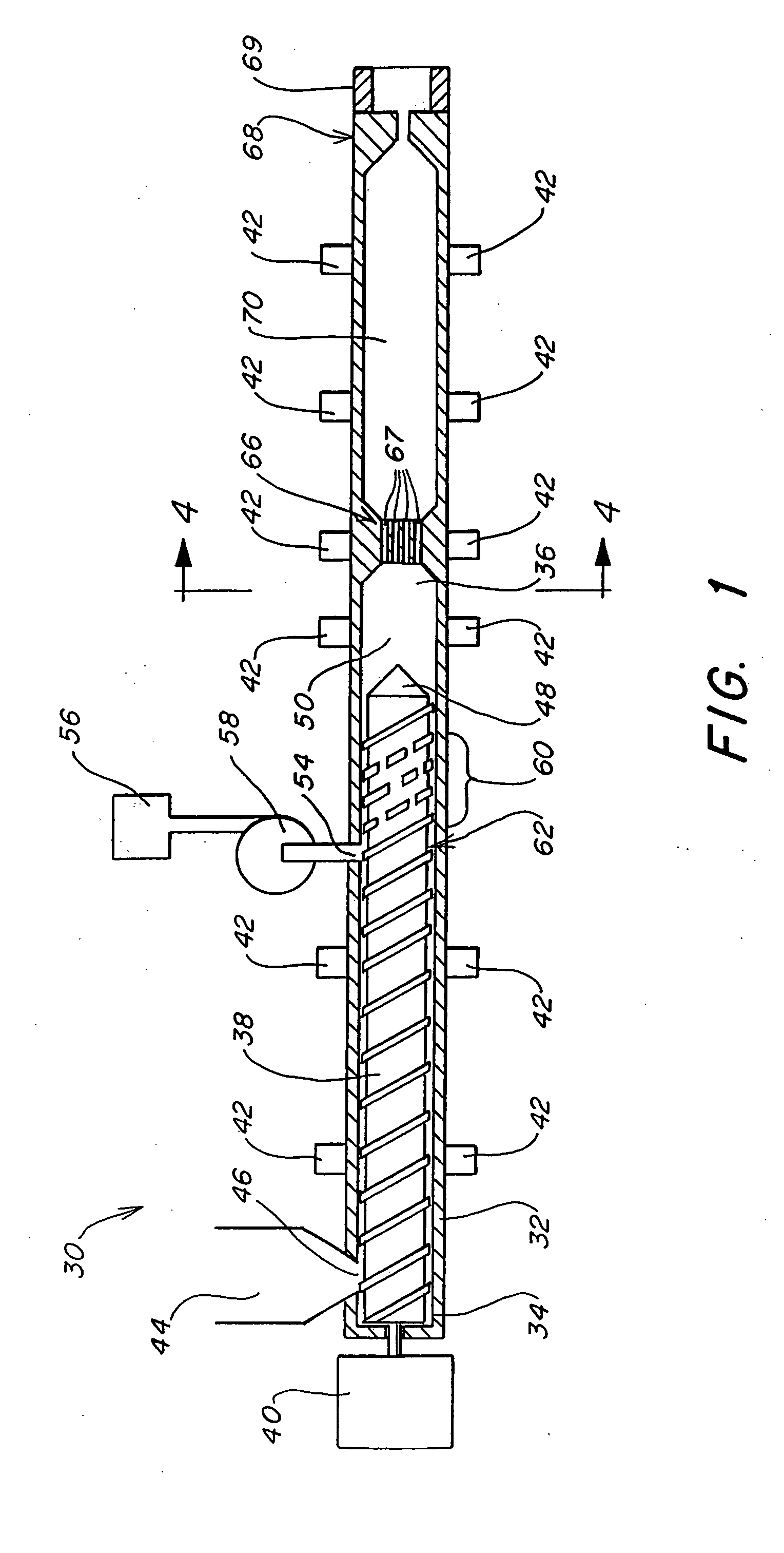
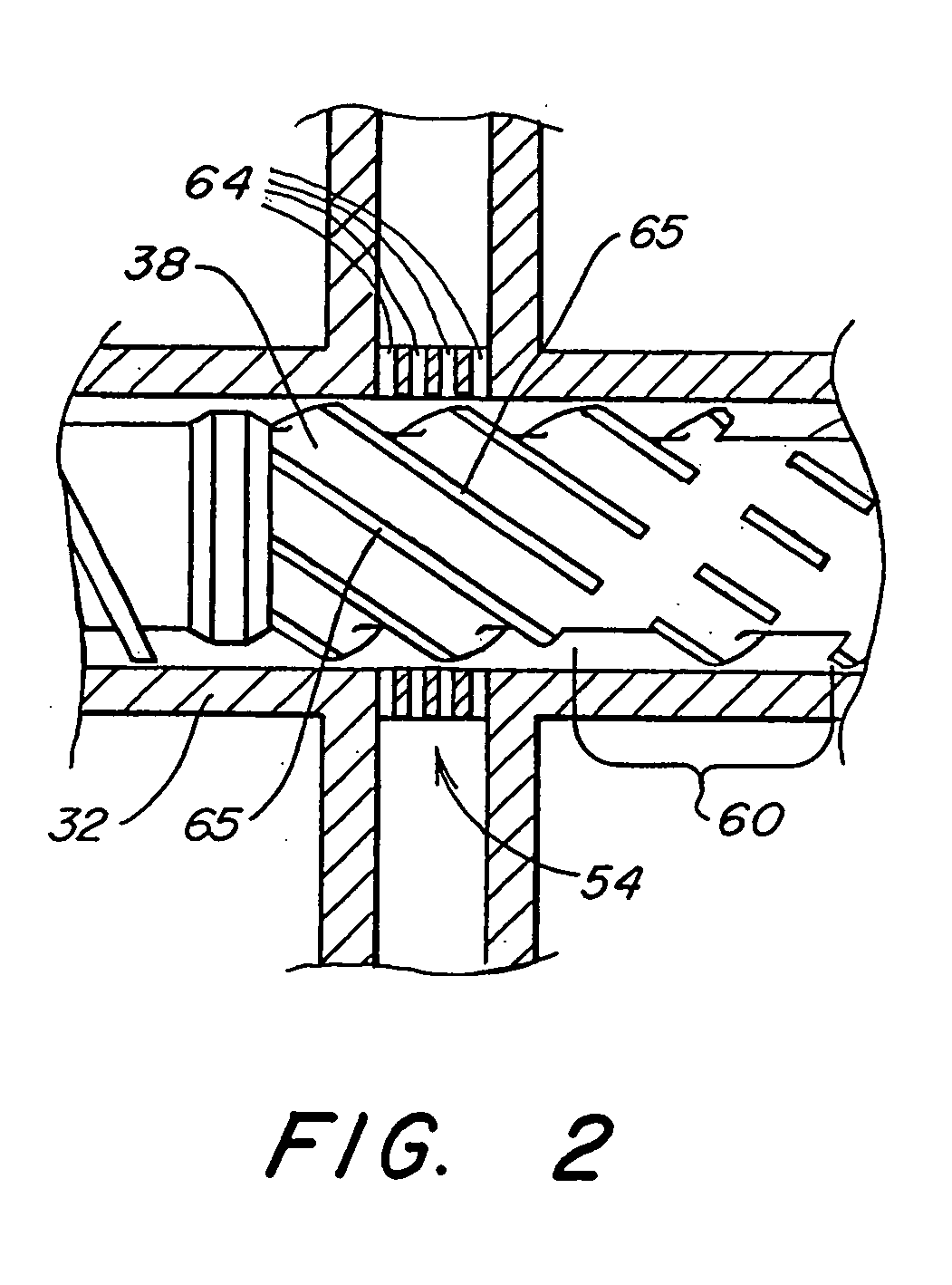
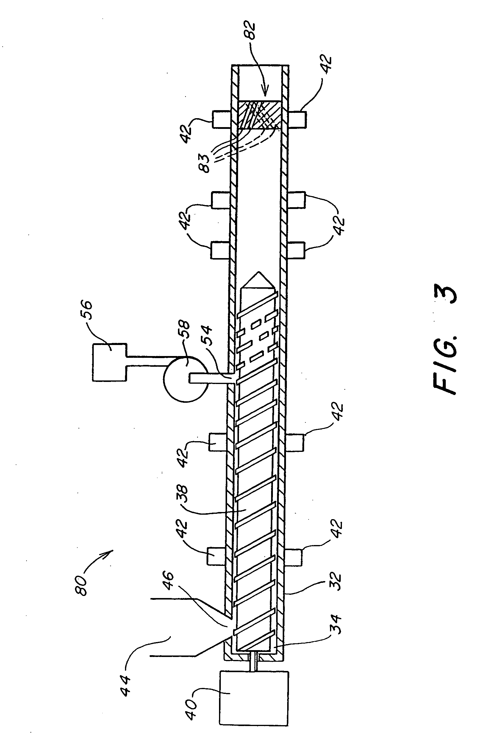
[0166] A tandem extrusion line (Akron Extruders, Canal Fulton, Ohio) was arranged including a 2 inch, 32 / 1 L / D primary extruder and a 2.5 inch, 34 / 1 L / D secondary extruder. An injection system for injection of CO2 into the primary was placed at a distance of approximately 20 diameters from the feed section. The injection system included 4 equally-spaced circumferentially, radially-positioned ports, each port including 176 orifices, each orifice of 0.02 inch diameter, for a total of 704 orifices.

[0167] The primary extruder was equipped with a two-stage screw including conventional first-stage feed, transition, and metering sections, followed by a multi-flighted (four flights) mixing section for blowing agent dispersion. The screw was designed for high-pressure injection of blowing agent with minimized pressure drop between the first-stage metering section and point of blowing agent injection. The mixing section included 4 fligh...

example 3

Extrusion of Microcellular, Flame-Retardant High-Density Polyethylene onto 24 AWG Solid Copper Wire

[0173] Polyethylene pellets (Union Carbide UNIGARD-HP™ DGDA-1412 Natural, 1.14 g / cc) were gravity-fed from the hopper of the primary screw into the extrusion system of Example 2. Primary screw speed was 15 RPM giving a total output (bleed and die) of approximately 15 lbs / hr of microcellular material. Secondary screw speed was 3 RPM. Barrel temperatures of the secondary extruder were set to maintain a melt temperature of 336° F. measured at the end of the secondary extruder. CO2 blowing agent was injected at a rate of 0.54 lbs / hr resulting in 3.6 wt % blowing agent in the melt. Pressure profile between the injection ports and the inlet of the crosshead was maintained between 3400 and 4040 psi. Approximately 1.2 lbs / hr fluid microcellular material precursor flowed through the crosshead, which could be controlled by adjustment of the bleed valve.

[0174]FIGS. 15 and 16 are photocopies of ...


PUM

PropertyMeasurementUnit
sizeaaaaaaaaaa
diameteraaaaaaaaaa
pressureaaaaaaaaaa

Abstract

Continuous polymeric extrusion nucleation systems and methods useful for making polymeric microcellular foamed materials, including crystalline and semi-crystalline polymeric microcellular materials, are provided. Pressure drop rate is an important feature in some embodiments, and the invention provides systems for controlling these and other parameters. One aspect involves a multiple-pathway nucleator that is separated from a shaping die by a residence chamber. Another aspect involves a die for making advantageously thick articles, including a multiple-pathway nucleation section. Microcellular material can be continuously extruded onto wire, resulting in a very thin, essentially closed-cell microcellular insulating coating secured to a wire. Other very thin microcellular products can be fabricated as well.

Description

RELATED APPLICATIONS [0001] This application commonly-owned, co-pending is a continuation of U.S. application Ser. No. 09 / 626,808, filed Jul. 27, 2000, which is a divisional of U.S. application Ser. No. 09 / 258,625, filed Feb. 26, 1999, which is a continuation of Int'l patent application serial no. PCT / US97 / 15088, filed Aug. 26, 1997, which claims priority to commonly-owned, co-pending U.S. provisional patent application Ser. No. 60 / 024,623 entitled “Method and Apparatus for Microcellular Extrusion”, filed Aug. 27, 1996 by Burnham, et al., to commonly-owned, co-pending U.S. provisional patent application Ser. No. 60 / 026,889, entitled “Method and Apparatus for Microcellular Extrusion”, filed Sep. 23, 1996 by Kim, et al, and to commonly-owned, co-pending U.S. patent application Ser. No. 08 / 777,709, entitled “Method and Apparatus for Microcellular Extrusion”, filed Dec. 20, 1996 by Kim, et al, each of which is incorporated herein by reference.FIELD OF THE INVENTION [0002] The present in...

Claims


Application Information

Patent Timeline
Patent Type & Authority Applications(United States)
IPC IPC(8): B29C44/32B29C44/34B29C44/46B29C48/06B29C48/07B29C48/29B29C48/30B29C48/74B29K105/04C08J9/00
CPCB29C44/322B29C44/3446B29C44/3473B29C44/348B29C44/461B29K2105/16B29C47/0016B29C47/0019B29C47/1063B29K2105/0005B29C47/1045B29C44/468B29C48/29B29C48/06B29C48/07B29C48/2886
Inventor BURNHAM, THEODORE A.CHA, SUNG WOONWALAT, ROBERT H.KIM, ROLAND Y.ANDERSON, JERE R.STEVENSON, JAMES F.SUH, NAM P.PALLAVER, MATTHEW
Owner TREXEL
Why Eureka
Try Eureka