Program/erase method for p-channel charge trapping memory device
a memory device and charge trapping technology, applied in the field of memory devices, can solve the problems of high power consumption, high power consumption, and change of status from “programmed” to “erased”
Active Publication Date: 2005-12-08
MACRONIX INT CO LTD
View PDF7 Cites 95 Cited by
- Summary
- Abstract
- Description
- Claims
- Application Information
AI Technical Summary
Benefits of technology
[0051] A memory device comprising memory cells according to the present invention has several advantages over conventional memory devices. First, because electron injection efficiency is generally higher than hole injection, a memory device according to the present invention has a higher efficiency and, therefore, higher speed, than those memory devices that are programmed / erased by hole injection. Measured by the ratio of gate current to drain current, the electron injection efficiency may reach 10−2.
[0052] Second, because electron tunneling causes much less damage to the tunneling oxide than hole tunneling, a memory device according to the present invention provides better data retention properties.
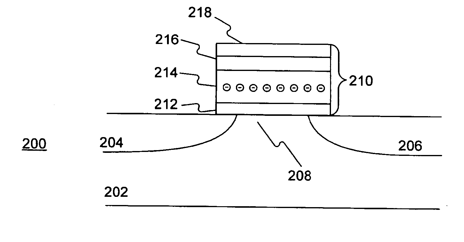
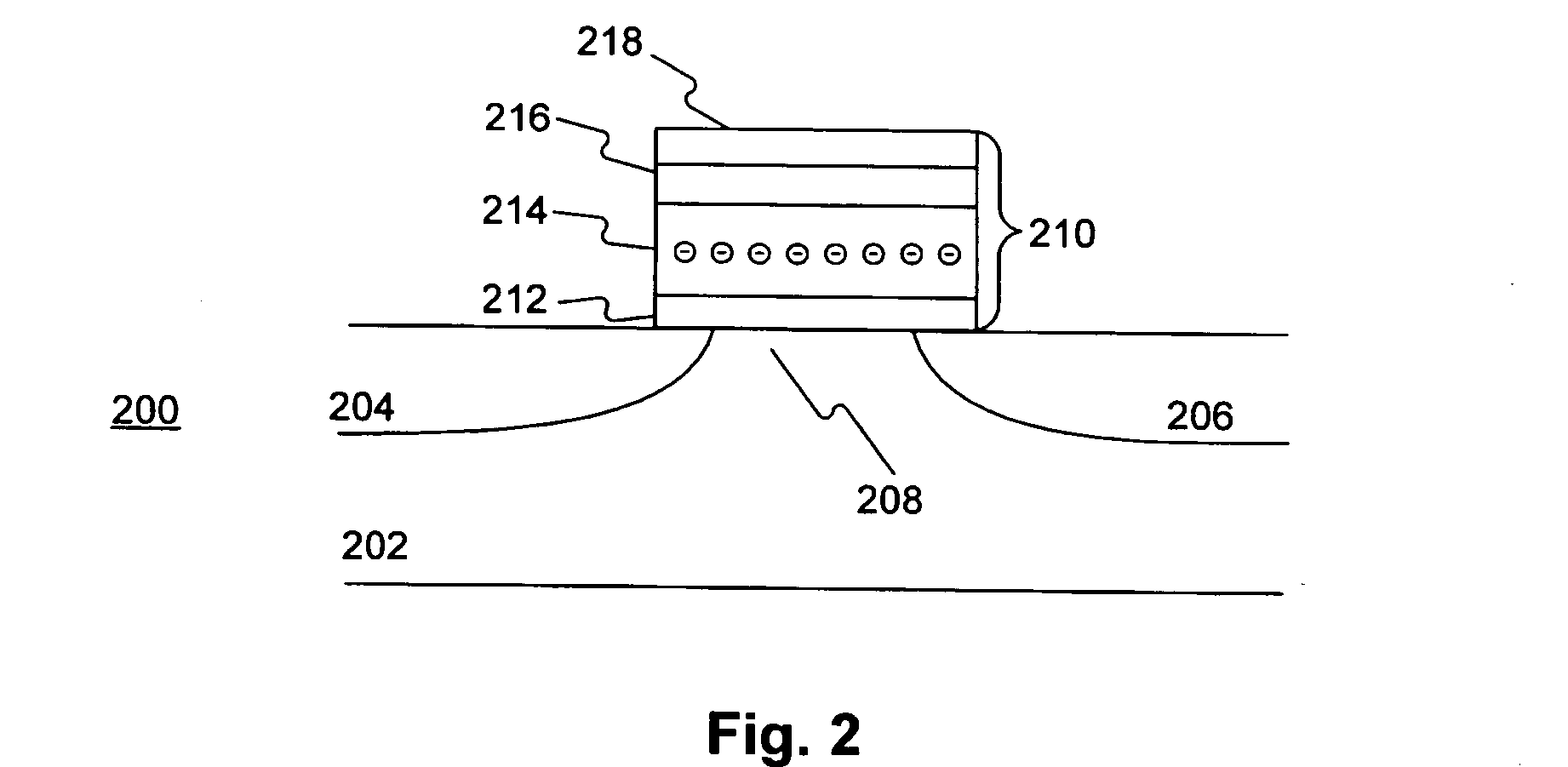
[0033]FIG. 2 shows a distribution profile of electrons in trapping layer 214 before memory cell 200 is programmed. It is to be understood that the electron profile shown in FIG. 2 is not drawn to scale. It is also to be understood that a MOS structure is generally symmetrical and the source and drain are interchangeable. Therefore, in the above and following descriptions, the source and drain of memory cell 200, or the first and second bit lines, may be interchanged without affecting the functions thereof or the scope of the present invention.
[0034] Because trapping layer 214 is non-conductive, when carriers tunnel into trapping layer 214, the carriers are trapped therein and become relatively immobile. By controlling the biases on control gate 218, source 204, and drain 206, it is possible to control into which part of trapping layer 214 the carriers tunnel. Therefore, trapping layer 214 may be divided into two parts, a first bit and a second bit, each for the storage of one bit of information. In one aspect, the first bit corresponds to the part of trapping layer 214 adjacent to the first bit line, or source 204, and the second bit corresponds to the part of trapping layer 214 adjacent to the second bit line, or drain 206. By controlling the part of trapping layer 214 into which the carriers tunnel, the first bit and the second bit may be respectively programmed, read, or erased. Since the source and drain of a MOS structure are generally interchangeable, the programming or reading method for the first bit of memory cell 200 may also be applied to program or read the second bit. Therefore, only the method for the first bit is described herein.
Problems solved by technology
However, certain problems are associated with the conventional flash memory, such as high power consumption and program and read disturbances.
High power consumption is due to high program and erasure voltages required to induce electron tunneling for program and erase operations.
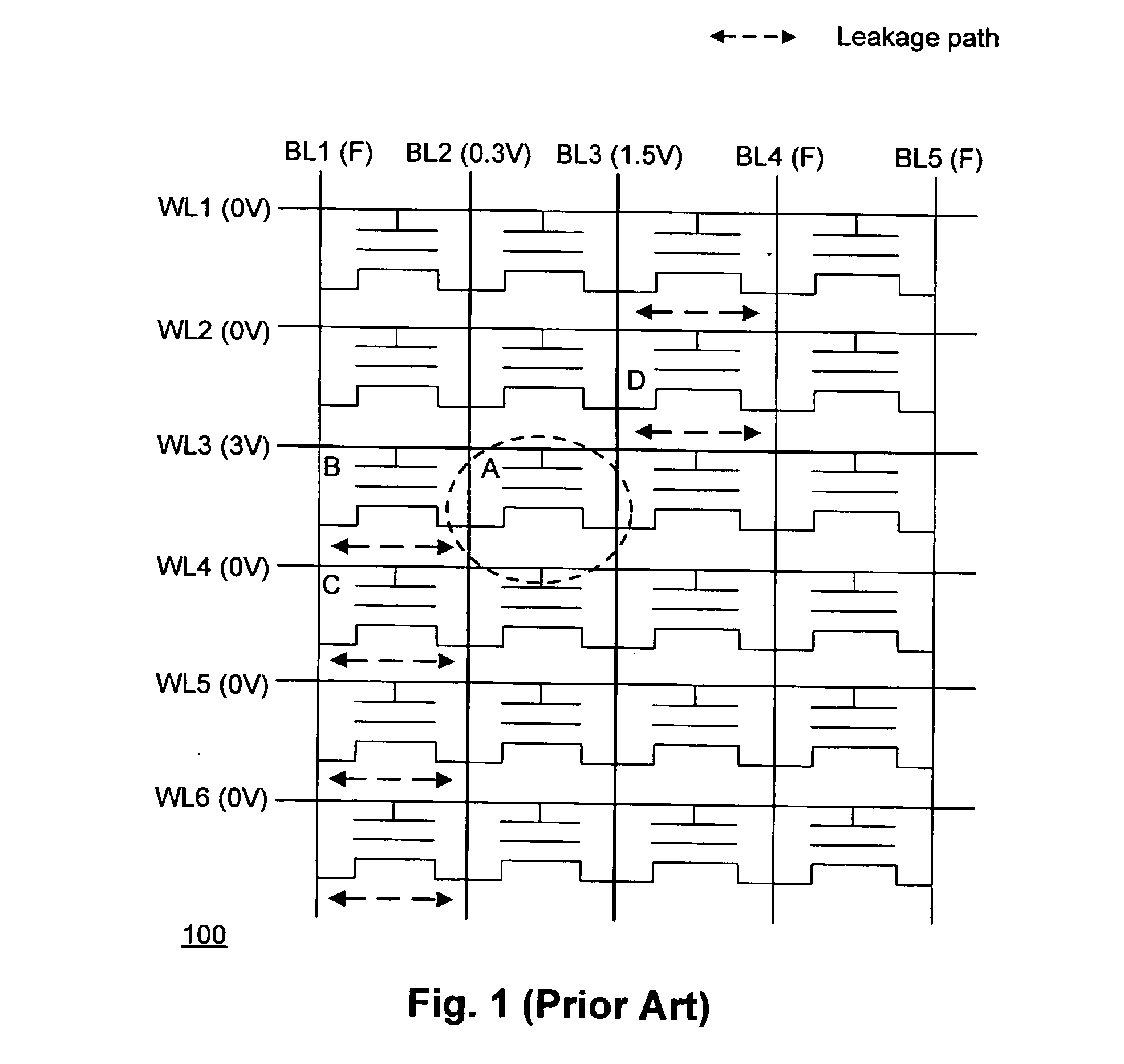
A disturbance occurs when one selected cell in the memory array is being read or programmed, another non-selected programmed memory cell sharing the same word line or bit line experiences current leakage caused by electron tunneling of the selected cell, and a loss of electrons stored in the floating gate of the non-selected memory cell may result in a change of status from “programmed” to “erased”.
In other words, a lower threshold voltage will result in a higher leakage current.
Method used
View moreImage
Smart ImageViewing Examples
Examples
first embodiment
[0026]FIG. 5 shows a memory device consistent with the present invention;
second embodiment
[0027]FIG. 6 shows a memory device consistent with the present invention; and
[0028]FIG. 7 shows a cross-sectional view of the memory device shown in FIG. 6 along line 6-6′.
Login to View More PUM
 Abstract
A method of operating a memory device is disclosed, wherein the memory device includes an n-type substrate and a plurality of memory cells formed thereon, each memory cell corresponding to a word line, a first bit line, and second bit line, and including a first bit portion and a second bit portion each for storing one bit of information. The method includes resetting a selected memory cell by applying a first negative bias to the word line of the selected memory cell and applying a ground bias to the first and second bit lines, and programming the first bit portion of the selected memory cell by applying a first positive bias to the word line of the selected memory cell, applying a second negative bias to the first bit line of the selected memory cell, and applying a ground bias to the second bit line of the selected memory cell.
Description
DESCRIPTION OF THE INVENTION [0001] 1. Field of the Invention [0002] This invention is in general related to a memory device, and more particularly, to a novel flash memory device that utilizes band-to-band tunneling induced hot electron injection. [0003] 2. Background of the Invention [0004] Memory devices for non-volatile storage of information have been widely in use. Examples of such memory devices include read only memory (ROM), programmable ROM (PROM), erasable programmable ROM (EPROM), electrically erasable programmable ROM (EEPROM), and flash EEPROM. A flash memory generally refers to a flash EEPROM, which may be erased in blocks of data instead of one byte at a time. [0005] A flash memory device generally includes an array of memory cells arranged in rows and columns. Each memory cell includes a MOS transistor structure having a gate, a drain, a source, and a channel defined between the drain and the source. The gate corresponds to a word line, and the drain or source corre...
Claims
Login to View More Application Information
Patent Timeline
 IPC IPC(8): H01L29/788H01L29/792H01L21/8247H01L27/115G11C16/04
CPCG11C16/0475G11C16/0483G11C16/0491
Inventor LUE, HANG-TING
Owner MACRONIX INT CO LTD
Features
- R&D
- Intellectual Property
- Life Sciences
- Materials
- Tech Scout
- Unparalleled Data Quality
- Higher Quality Content
- 60% Fewer Hallucinations
Learn More Browse by: Latest US Patents, China's latest patents, Technical Efficacy Thesaurus, Application Domain, Technology Topic, Popular Technical Reports.
© 2025 PatSnap. All rights reserved.Legal|Privacy policy|Modern Slavery Act Transparency Statement|Sitemap|About US| Contact US: help@patsnap.com


