
Catalytic reactor for hydrogen generation systems

Inactive Publication Date: 2005-12-15
MILLENNIUM CELL
View PDF6 Cites 53 Cited by
  • Summary
  • Abstract
  • Description
  • Claims
  • Application Information

AI Technical Summary

Benefits of technology

[0010] Broadly, the present invention improves the operational performance of catalytic reactors and the hydrogen generating systems in which such reactors are disposed by incorporating one or more performance enhancing elements in the reactor. These elements include:
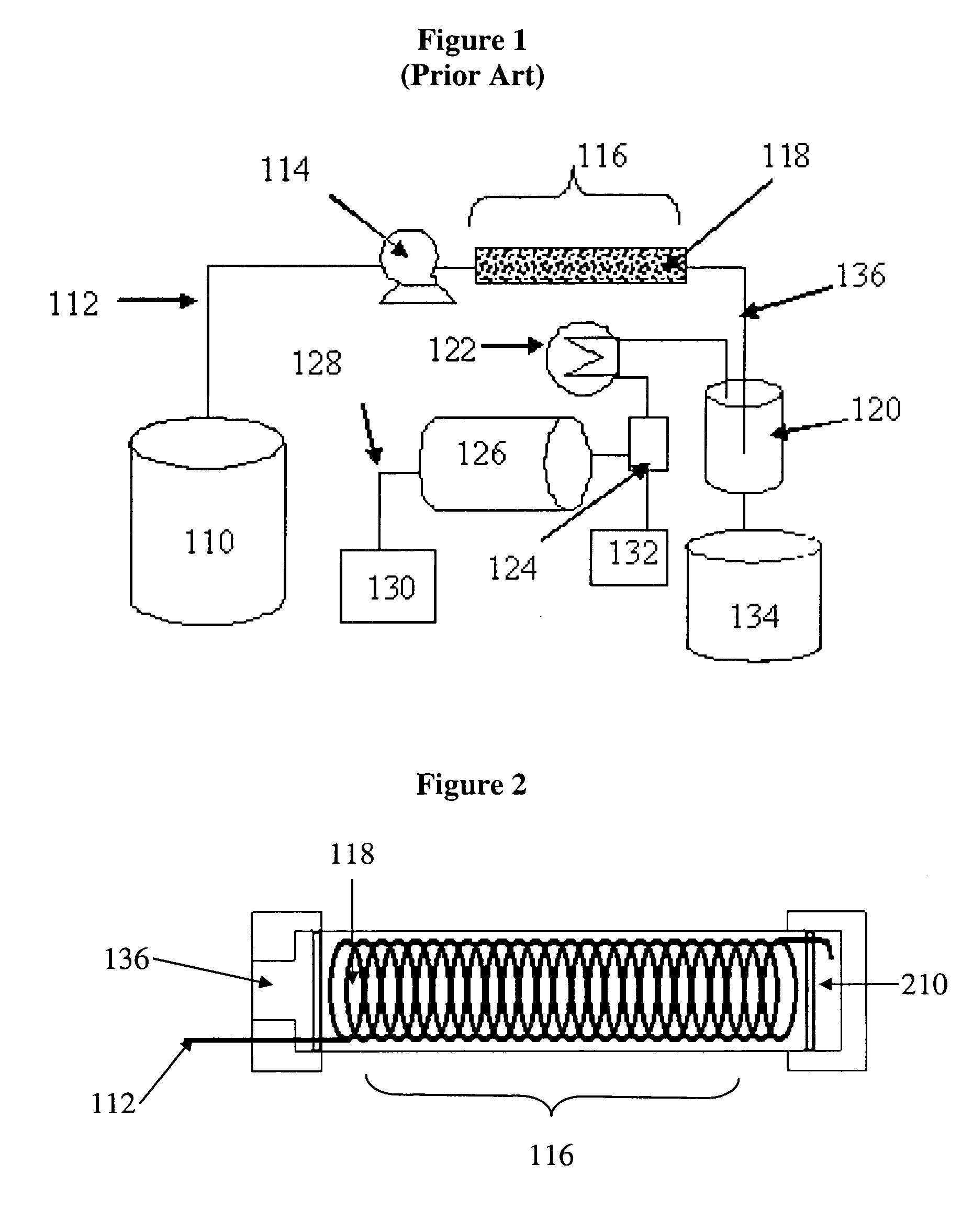
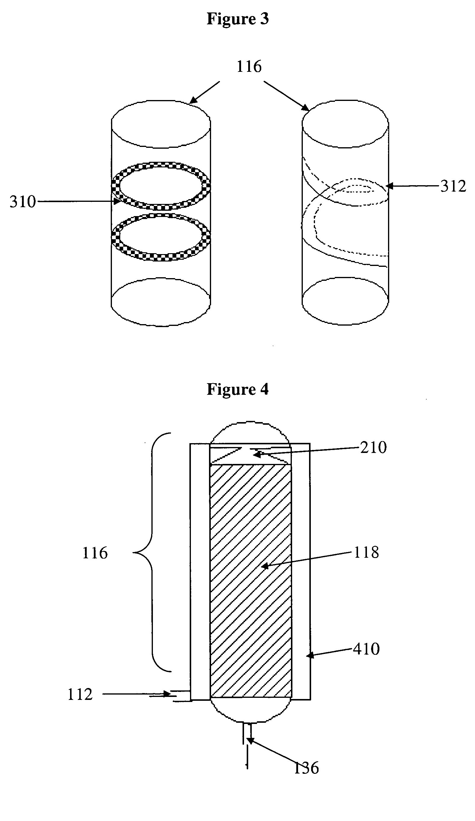
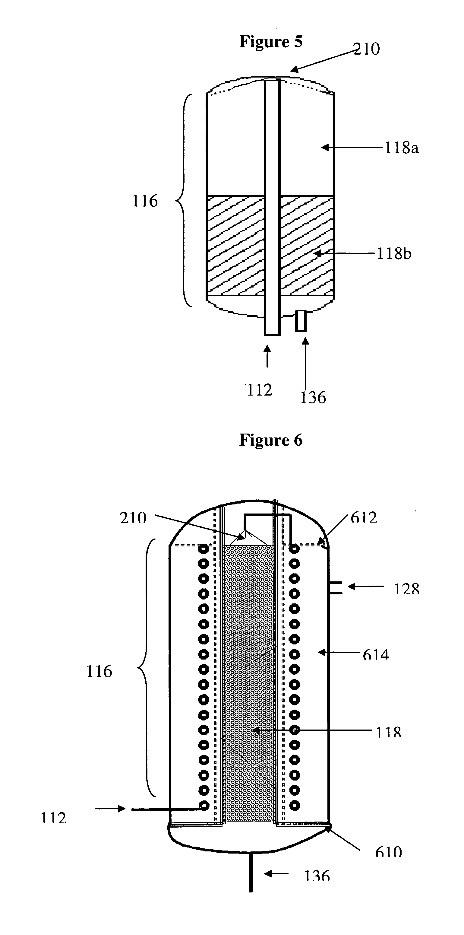
[0015] As described hereinbelow, the use of a heat exchanging element to preheat the fuel solution enhances the rate of reaction between the fuel and the catalyst. The use of one or more fuel diffusing elements within the reactor enhances the contact of the fuel solution with the catalyst so as to increase the rate of hydrogen generation. The use of two or more different catalytic materials having different hydrogen generating capabilities within the reactor can enhance certain operational characteristics of the reactor, e.g., start-up response time. The use of a membrane capable of withstanding pressures of at least 50 psig enhances the operation of the reactor by providing separation of the generated hydrogen from the liquid fuel within the catalytic reactor, eliminating or reducing the size of downstream gas / liquid separation elements, while also providing the higher hydrogen generation rates attainable at such pressures. Each of the foregoing elements can be used singularly or in any combination, as desired, and the present invention is compatible with use in otherwise conventional hydrogen generation systems, including such systems which recycle the water output of the fuel cell to which the hydrogen is delivered. Such recycling of the water advantageously utilizes what is normally considered a waste product of fuel cell operation dilute highly concentrated fuel solutions that are stored. The storage of highly concentrated fuels reduces the size of the required fuel storage tank in a given application.

Problems solved by technology

Hydrogen is the fuel of choice for fuel cells, however, its widespread use is complicated by the difficulties in storing the gas.
As the most reactive catalyst metals are the relatively expensive Group VIII metals such as platinum, palladium, and ruthenium, the catalyst is a major contributor to the cost of a hydrogen generating system.
In addition, these large reactors demonstrate significant fuel hold-up of about 80% of reactor volume.
When the demand of the fuel cell rapidly changes from high H2 flow rates to low or zero H2 flow rates, a considerable amount of fuel remains in the reactor.
Any hydrogen generated by this residual fuel that is not immediately needed by the fuel cell must be vented from the reactor chamber as it cannot remain in the chamber without posing a potential safety risk.
Attempts to develop improved reactor technology for hydrogen generation from metal hydride fuels have not yet addressed all of these issues.
The loosely packed or baffled catalyst beds of those systems lead to considerable back mixing and channel leak that contribute to low fuel conversion and low reactor throughput.

Method used


Image

  • Catalytic reactor for hydrogen generation systems
  • Catalytic reactor for hydrogen generation systems
  • Catalytic reactor for hydrogen generation systems

Examples


example 1

[0046] A tubular reactor having a 1.0″ outside diameter (“o.d.”) and a length of 7″ (volume of 60 mL) was used for reactor performance tests. The supported catalyst systems were prepared as described in U.S. Pat. No. 6,534,033. Two catalyst systems were tested: ruthenium-cobalt on nickel metal fiber (RuCo / Ni) with a nominal loading of 1.2 wt-% Ru and 3 wt-% Co and cobalt-zinc on nickel metal fiber (CoZn / Ni) with a nominal loading of 3 wt-% Co and 3 wt-% Zn.

[0047] Reactor A was packed with 55 g of RuCo / Ni catalyst; Reactor B was packed with 55 g of CoZn / Ni catalyst. Reactor C was packed with two catalyst beds in accordance with FIG. 5 but Without a heat exchange element; 25 g of RuCo / Ni catalyst was placed in the first portion of the reactor 116 (catalyst bed 118a) and 25 g of CoZn / Ni catalyst was placed in the second portion of the reactor 116 (catalyst bed 118b). Reactors were operated horizontally without insulation and without integration of heat exchanger and membrane elements ...


PUM


Abstract

The operating characteristics of catalytic reactors used in systems which generate hydrogen from the contact of a fuel with a catalyst are enhanced by such reactors incorporating one or more of group of elements consisting of (a) a heat exchanging element that preheats the fuel solution prior to its contact with the catalyst, (b) one or more liquid diffusing elements which distributes the flow of fuel over the catalyst so as to increase the generation hydrogen from such contact, (c) multiple catalysts having different hydrogen generating characteristics and d) a membrane capable of operating at pressures equal to or greater than 50 psig which surrounds catalytic material in the reactor and separates the generated hydrogen from the fuel.

Description

FIELD OF THE INVENTION [0001] The present invention relates to the design of a catalytic reactor used in a system for generating hydrogen from a fuel solution, such generation being promoted by contact of the fuel solution with catalytic material in the reactor. BACKGROUND OF THE INVENTION [0002] Hydrogen is the fuel of choice for fuel cells, however, its widespread use is complicated by the difficulties in storing the gas. Many hydrogen carriers, including hydrocarbons, metal hydrides, and chemical hydrides are being considered as hydrogen storage and supply systems. In each case, specific systems need to be developed in order to release the hydrogen from its carrier, either by reformation as in the case of hydrocarbons, desorption from metal hydrides, or catalyzed hydrolysis of chemical hydrides. [0003] One of the more promising systems for hydrogen storage and generation utilizes borohydride compounds as the hydrogen storage media. Sodium borohydride (NaBH4) is of particular inte...

Claims


Application Information

Patent Timeline
IPC IPC(8): B01J8/02B01J8/04B01J19/24B01J19/26C01B3/02C01B3/06
CPCB01J8/0278B01J8/0285B01J8/0453B01J19/2475B01J19/26B01J2208/00132Y02E60/364B01J2208/00176B01J2208/00203B01J2208/00504B01J2208/0084C01B3/065Y02E60/362B01J2208/00141Y02E60/36
Inventor ZHANG, QINGLINSMITH, GREGORY M.HONG, ZONGXUAN
Owner MILLENNIUM CELL
Learn More