

Spray coating of cathode onto solid electrolyte capacitors
- Summary
- Abstract
- Description
- Claims
- Application Information
AI Technical Summary
Benefits of technology
Problems solved by technology
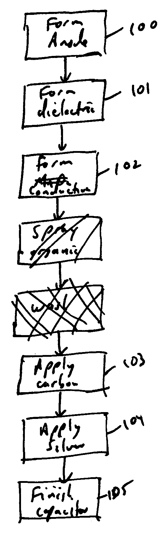
Method used
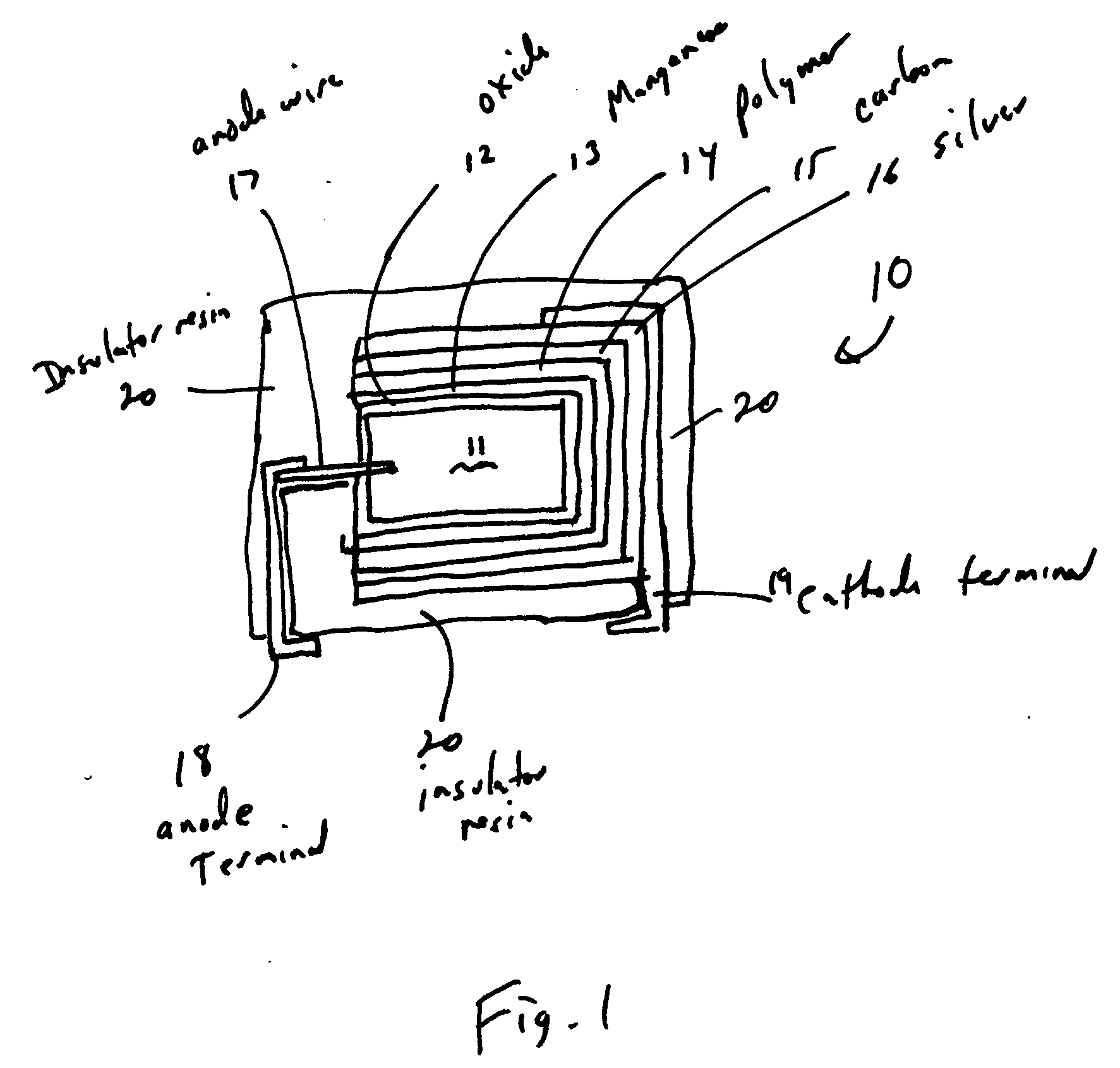
Image


Examples
example 1
[0047] Commercially available capacitor grade tantalum powder was pressed into a pellet 0.133×0.190×0.034 inches (3.38×4.83×0.864 mm) and sintered to form a batch of anodes. The dielectric oxide layer was formed by applying 7.5 volts in an aqueous phosphoric acid electrolyte. The dielectric surfaces were coated with intrinsically conductive PEDT using a chemical oxidation dip process. A matrix experiment was run comparing ESR of carbon dip vs. carbon spray and silver dip versus silver spray. The data, provided in Table 1, indicates that ESR was lower with carbon spray than carbon dip with an average ESR improvement of 0.84 milliohms. The average ESR was lower for silver spray than for a silver dip by an average of 2.54 milliohms. The lowest ESR was obtained when both carbon and silver were sprayed which is represented as a 3.43 milliohm improvement in ESR versus both layers formed by dipping.
TABLE 1ESR results for Example 1 (milliohms)Silver DipSilver SprayAverage (Carbon)Carbon D...
example 2
[0048] Commercially available capacitor grade tantalum powder was pressed into a pellet 0.133×0.190×0.034 inches (3.38×4.83×0.864 mm) and sintered to form a batch of anodes. The dielectric oxide layer was formed by applying 9.0 volts in an aqueous phosphoric acid electrolyte. The dielectric surfaces were coated with an intrinsically conductive polymer PEDT using a chemical oxidation dip process. Carbon was applied by dipping in a carbon suspension. Four randomized samples were pulled and silver was applied to two samples by dipping and two samples by spraying. The four groups were encapsulated with a thermoset epoxy using a transfer molding process. Subsequent to the molding operation the four groups were passed through an infrared oven to simulate the process by which the components are mounted to a circuit board. ESR was measured after encapsulation and after the infrared pass. The results are summarized in Table 2.
TABLE 2ESR results for Example 2ESR afterEncapsul-ESR afterESR i...
example 3
[0050] Nine random samples were pulled from a batch of 0.133×0.190×0.034 inches (3.38×4.83×0.864 mm) pellet anodes after application of conductive polymer PEDT, by a chemical oxidation process, to demonstrate the relationship between carbon buildup and ESR. Carbon solutions are commercially available from various vendors. The data indicates that ESR was proportional to carbon buildup and that the thinnest carbon layers were obtained by spraying the carbon. Elimination of the carbon layer resulted in higher ESR due to the incompatibility of the conductive polymer / silver interface as indicated in Table 3.
TABLE 3ESR and Carbon Thickness (microns)Application ProcessESR (milliohms)Thickness (micron)No Carbon10.040Thin Spray Coat7.210.90(2 passes)Medium Spray Coat7.330.95(4 passes)Thick Spray Coat7.411.15(8 passes)1 dip, sponge blot7.551.811 dip, single vacuum7.752.641 dip, double vacuum7.963.051 dip, no blot8.495.633 dips, no blot14.4221.955 dips, no blot25.8854.75
PUM
| Property | Measurement | Unit |
|---|---|---|
| Electrical conductor | aaaaa | aaaaa |
Abstract
Description
Claims
Application Information