Thermal drill cuttings treatment with weir system

a weir system and drilling cutting technology, applied in the direction of centrifuges, borehole/well accessories, separation processes, etc., can solve the problems of increasing wear on mud pumps and other mechanical equipment used for drilling, increasing the difficulty of cuttings on-site at an offshore rig, and increasing the cost of operation, so as to reduce the size of condensing and particulate collection equipment and high hydrocarbon contamination

Inactive Publication Date: 2005-12-22
VARCO I P INC
View PDF70 Cites 59 Cited by
  • Summary
  • Abstract
  • Description
  • Claims
  • Application Information

AI Technical Summary

Benefits of technology

[0015] To effect vaporization of the water and hydrocarbons from the material while in the dryer, the material is heated to temperatures required to vaporize those water and hydrocarbon constituents. These temperatures are typically between 300° F. and 900° F. Material leaving the dryer is, optionally, mixed with water for cooling and added moisture.
[0016] Either indirect or direct fired dryers may be used. The use of ind...

Problems solved by technology

If drilled solids are not removed from the mud used during the drilling operation, recirculation of the drilled solids can create weight, viscosity, and gel problems in the mud, as well as increasing wear on mud pumps and other mechanical equipment used fo...

Method used


Image

  • Thermal drill cuttings treatment with weir system
  • Thermal drill cuttings treatment with weir system
  • Thermal drill cuttings treatment with weir system

Examples


Embodiment Construction

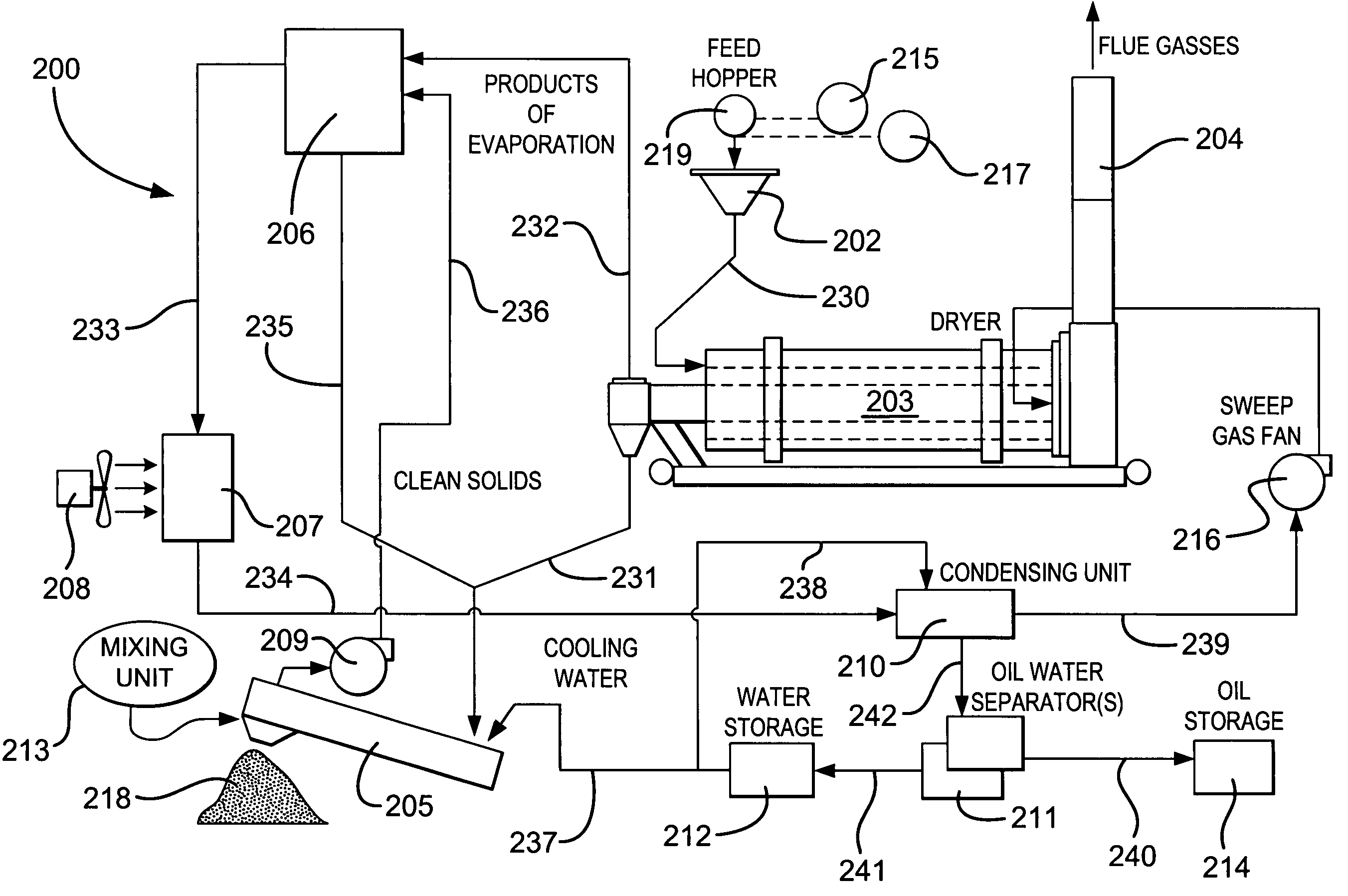
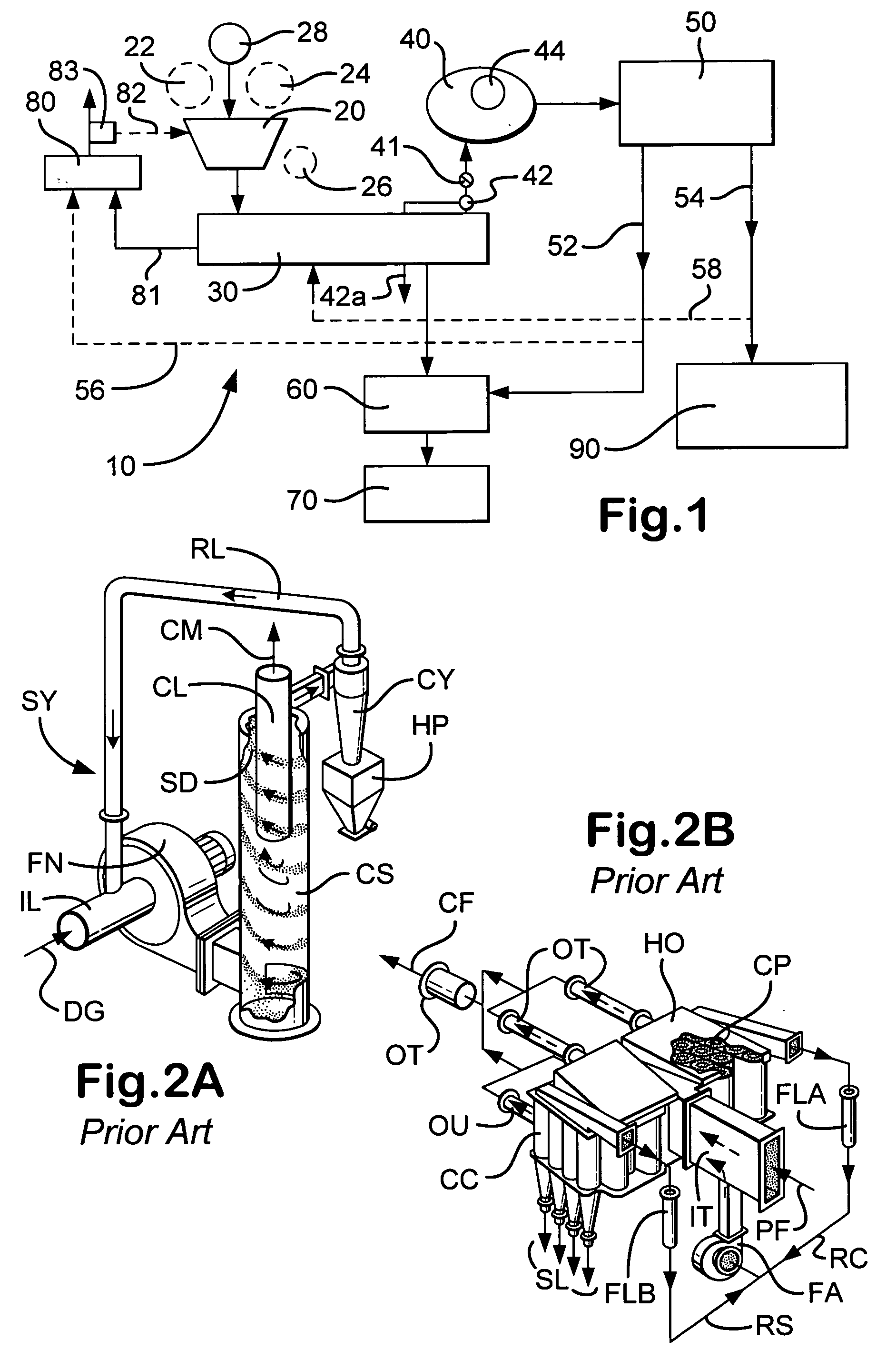
[0044] As shown in FIG. 1, one particular embodiment of a system 10 according to the present invention has a feed hopper 20; a dryer 30; a condenser 40; an oil / water separator 50; a rehydration system 60; a discharge 70; an exhaust stack 80; and an oil processor 90.

[0045] Initially, cuttings in a drilling fluid are processed by a rig's shaker system, producing fluid, soil, and oily contaminated cuttings and solids (collectively “oily solids”). These oily solids in a slurry of solids, oil and water are fed to the feed hopper 20 (e.g. from: an end loader; conveyor belt; auger; vacuum system from the shakers; mud cleaner, hydrocyclone and / or centrifuge).

[0046] The feed hopper may include appropriate crushers, shredders, and / or classifiers. A “grizzly unit” (i.e. a screening system with relatively large openings) may be used positioned over the top of the feed hopper. The grizzly unit removes large clay balls and / or large pieces of rubble which are sent to a shredder. Optionally, sepa...


PUM

PropertyMeasurementUnit
Fractionaaaaaaaaaa
Fractionaaaaaaaaaa
Mass flow rateaaaaaaaaaa

Abstract

A method for treating material, the material contaminated with contaminants, the method including: introducing material with contaminants to a system for remediation including a thermal treatment system, a quench system, a weir tank system and a condensing system; feeding a slurry of the material to the thermal treatment system and heating the material therein producing heated discharge solids and a discharge stream with liquid and solids therein; optionally, discharging the heated discharge solids and feeding them to a mill system; feeding the discharge stream to a quench system producing a cooled discharge stream which is fed to the weir tank system; the weir tank system having a clean side and a dirty side; the cooled discharge stream fed to the dirty side of the weir tank system, and from the weir tank system producing at least one stream of cleaned liquid and a stream with contaminants therein; and, in one particular aspect, remediating drilled cuttings material using such a method.

Description

RELATED APPLICATION [0001] This is a continuation-in-part of U.S. application Ser. No. 10 / 051,314 filed Jan. 16, 2002.BACKGROUND OF THE INVENTION [0002] 1. Field of the Invention [0003] The present invention is directed to systems and methods for cleaning contaminated soil and, in one particular aspect, to cleaning wellbore drilling cuttings, either on-shore or offshore. [0004] 2. Description of Related Art [0005] In a variety of industrial methods, operations, and processes soil becomes contaminated with contaminants such as hydrocarbons and other volatile organic materials and substances. The prior art discloses a wide range of systems and methods for cleaning such soil and for disposal of such contaminants. [0006] Drilling fluids used in hydrocarbon well drilling, as well known in the prior art, pick up solid cuttings and debris which must be removed if the fluid is to be re-used. Drilling fluid, called “mud,” is typically either water based or oil-based. “Oil” includes, but is n...

Claims


Application Information

Patent Timeline
IPC IPC(8): B01D17/02B01D21/24C02F1/02E21B21/06
CPCB01D17/0211B01D21/2444B01D21/2461E21B21/066
Inventor STRONG, GARY S.PIERCE, DALE A.STONE, LYNDONGADDIS, CLIFFWOOD, BRADFORD R.SEYFFERT, KENNETH W.LEE, CECIL
Owner VARCO I P INC
Why Eureka
Try Eureka