Transcutaneous energy transfer primary coil with a high aspect ferrite core

a technology of ferrite core and energy transfer coil, which is applied in the direction of coils, electrical equipment, therapy, etc., can solve the problems of erratically or not functioning devices, inability to provide any output power to implanted devices, and power fluctuations and surges in implant devices, etc., to achieve greater power coupling efficiency and more elliptical cross section

Inactive Publication Date: 2005-12-29
ETHICON ENDO SURGERY INC
View PDF50 Cites 224 Cited by
  • Summary
  • Abstract
  • Description
  • Claims
  • Application Information

AI Technical Summary

Benefits of technology

[0018] The invention overcomes the above-noted and other deficiencies of the prior art providing a transcutaneous energy transfer (TET) system that includes a primary coil having a magnetic flux shaping member centered within its circular diameter, thereby forming a toroidal magnetic flux field with an implanted secondary coil in a patient that is more elliptical in cross section. Thereby, greater power coupling efficiency is achieved, enabling medical implants to be placed at greater depths. Thus, applications such as remotely controllable adjustable gastric bands for the morbidly obese may be used without having to resort to inconveniently high power levels nor to having to embed separate secondary coils near the surface of the dermal layer.

Problems solved by technology

Variations in the spacing can cause changes in the AC magnetic field strength reaching the secondary coil, in turn causing power fluctuations and surges in the implant device.
Variations in the supplied power, such as sudden changes in voltage or current levels, may cause the device to perform erratically or fail to function at all.
Accordingly, one issue associated with conventional TET systems is that the physical displacement of either the primary or secondary coils from an optimum coupling position may cause an unacceptable effect on the output power supplied to the implanted device.
While effective, it is desirable to avoid having to adjust the fluid volume with a syringe needle since an increased risk of infection may result, as well as inconvenience and discomfort to the patient.
Although such TET powering of an implant, such as to recharge batteries, is a generally known procedure, using TET for an artificial sphincter system, such as an adjustable gastric band, presents a number of challenges.
A major challenge in using TET thus is transferring magnetic energy between the primary and secondary coils through this thick layer of tissue, which thus reduces the effective amount of power transferred to the implant.
While providing advantages for external sources of electromagnetic interference, such shields are not believed to substantially assist in directing the magnetic flux to the secondary coil of an implanted medical device.
While the shield described in U.S. Pat. No. 6,389,318 provided some shaping of the magnetic flux from the primary coil, one undesirable characteristic thereof was that the magnetic flux was flattened, providing less efficient power coupling to deeply embedded implantable devices.
It would be undesirable to implant metal pellets for a number of reasons.
First, in the morbidly obese patient, it may require a significant amount of pellets to seed the flux path.
Second, the patient may object to this permanent implantation.
Third, being ferrous objects, tissue damage or discomfort may result if the patient were in the presence of a strong magnetic field typical of a Magnetic Resonance Imaging (MRI) machine.
Fourth, these ferrous objects would create artifacts that would hamper diagnostic imaging such as MRI and CT.
Fifth, the chemical or physical properties of these pellets may have a deleterious effect on the dermis.
It is further inconvenient to shape the magnetic flux as described in U.S. Pat. No. 5,715,837 with opposing horseshoe shaped ferrite cores insofar as it is desirable to eliminate such mass from an implanted device to make it smaller.
However, it is undesirable to have an exposed implant that tends to allow infections.
In addition, use of a transformer instead of TET as in this application also makes the implant not compatible with MRI machines.

Method used


Image

  • Transcutaneous energy transfer primary coil with a high aspect ferrite core
  • Transcutaneous energy transfer primary coil with a high aspect ferrite core
  • Transcutaneous energy transfer primary coil with a high aspect ferrite core

Examples


Embodiment Construction

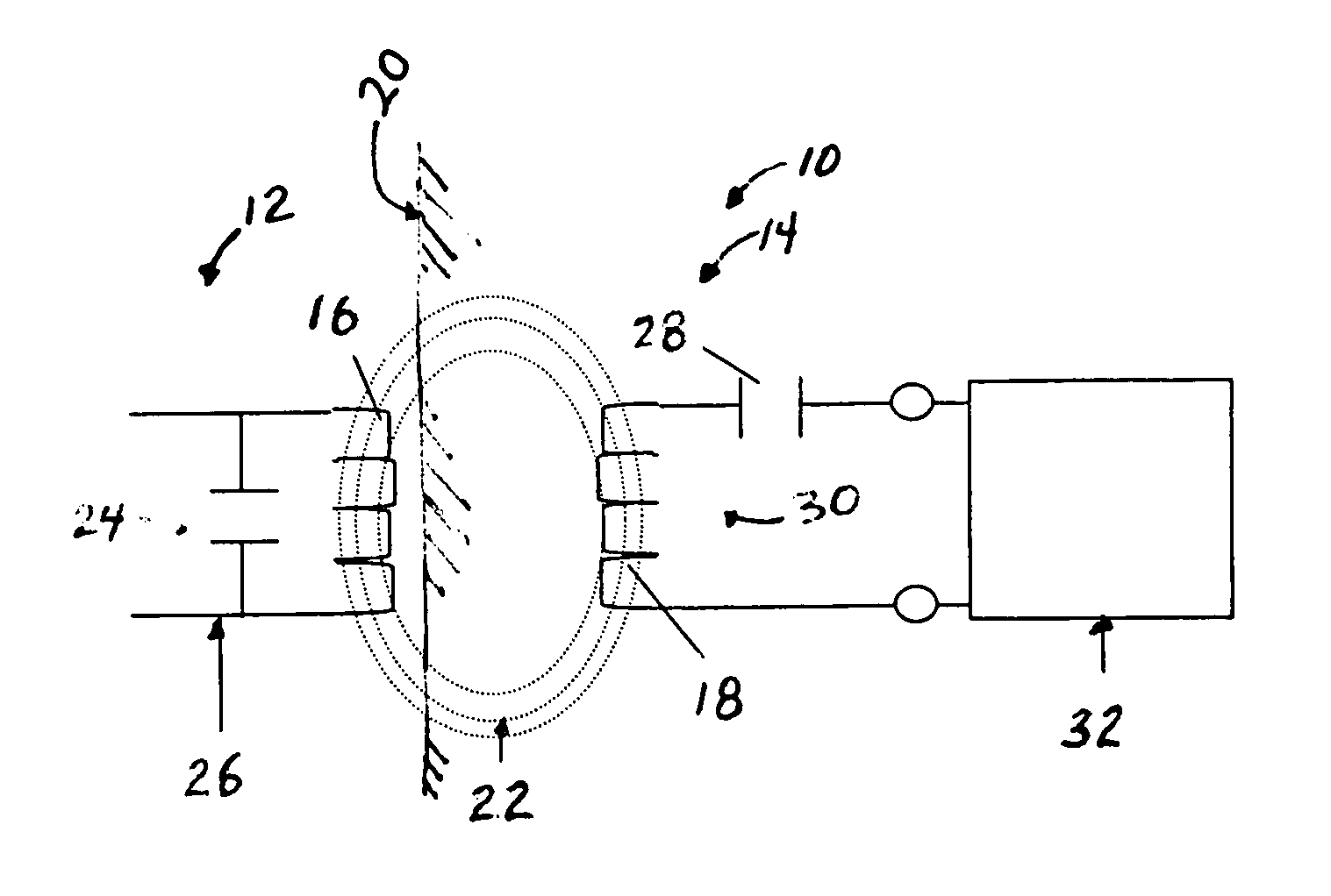
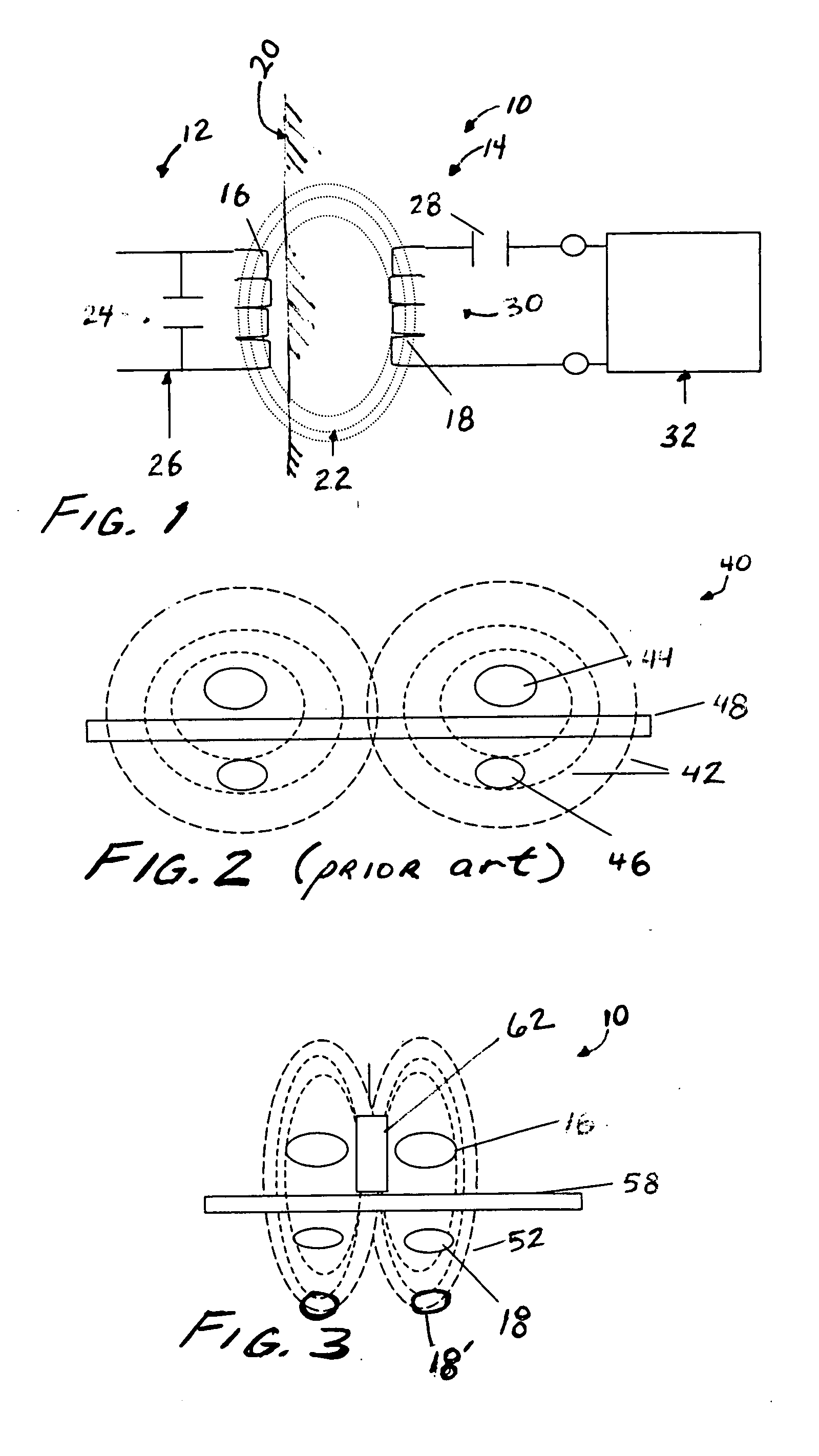
[0028] Referring now to the drawings in detail, wherein like numerals indicate the same elements throughout the views, FIG. 1 depicts the relationship between a transcutaneous energy transfer (TET) system 10 that has an external device 12 and an implanted device 14. The external device 12 includes a primary coil 16 that is external to a patient. The implanted device 14 includes a secondary coil 18 that inductively receives power from the primary coil 16 transcutaneously through a dermal layer 20 of the patient, as depicted by alternating current (AC) magnetic flux lines 22. The primary coil 16 is connected in parallel with capacitance 24 to form a resonant parallel tank circuit 26. The AC magnetic flux 22 generated by the resonant tank circuit 26 is collected by secondary coil 18, which is connected in series with a secondary capacitance 28 to form a secondary resonant series tuned tank circuit 30, which delivers power to implant circuitry 32.

[0029] As an example of an implanted de...


PUM


Abstract

Adjustable gastric band implants contain a hollow elastomeric balloon with fixed end points encircling a patient's stomach just inferior to the esophago-gastric junction. These balloons can expand and contract through the introduction of saline solution into the balloon. In current bands, this saline solution must be injected into a subcutaneous port with a needle to reach the port located below the skin surface. The port communicates hydraulically with the band via a catheter. As an alternative to using a percutaneously accessed injection port, a system for regulating the flow of saline that is totally implanted may rely upon bi-directionally pumping fluid from an implant device. This system instead transfers AC magnetic flux energy from an external primary coil to a secondary coil that powers the pump in the implanted reservoir. A magnetically permeable rod centered within the primary coil increases power coupled to the secondary coil.

Description

CROSS REFERENCE TO RELATED APPLICATIONS [0001] The present application is related to four co-pending and commonly-owned applications filed on even date herewith, the disclosure of each being hereby incorporated by reference in their entirety, entitled respectively: [0002]“MEDICAL IMPLANT HAVING CLOSED LOOP TRANSCUTANEOUS ENERGY TRANSFER (TET) POWER TRANSFER REGULATION CIRCUITRY” to William L. Hassler, Jr., Ed Bloom, Ser. No. ______; [0003]“SPATIALLY DECOUPLED TWIN SECONDARY COILS FOR OPTIMIZING TRANSCUTANEOUS ENERGY TRANSFER (TET) POWER TRANSFER CHARACTERISTICS” to Reshai Desai, William L. Hassler, Jr., Ser. No. ______; [0004]“LOW FREQUENCY TRANSCUTANEOUS TELEMETRY TO IMPLANTED MEDICAL DEVICE” to William L. Hassler, Jr., Ser. No. ______; and [0005]“LOW FREQUENCY TRANSCUTANEOUS ENERGY TRANSFER TO IMPLANTED MEDICAL DEVICE” to William L. Hassler, Jr., Daniel F. Dlugos, Jr., Ser. No. ______.FIELD OF THE INVENTION [0006] The present invention relates, in general, to medically implantable...

Claims


Application Information

Patent Timeline
Patent Type & Authority Applications(United States)
IPC IPC(8): A61N1/378
CPCA61N1/3787H01F5/04
Inventor GIORDANO, JAMES R.DLUGOS, DANIEL F. JR.HASSLER, WILLIAM L. JR.
Owner ETHICON ENDO SURGERY INC
Why Eureka
Try Eureka