

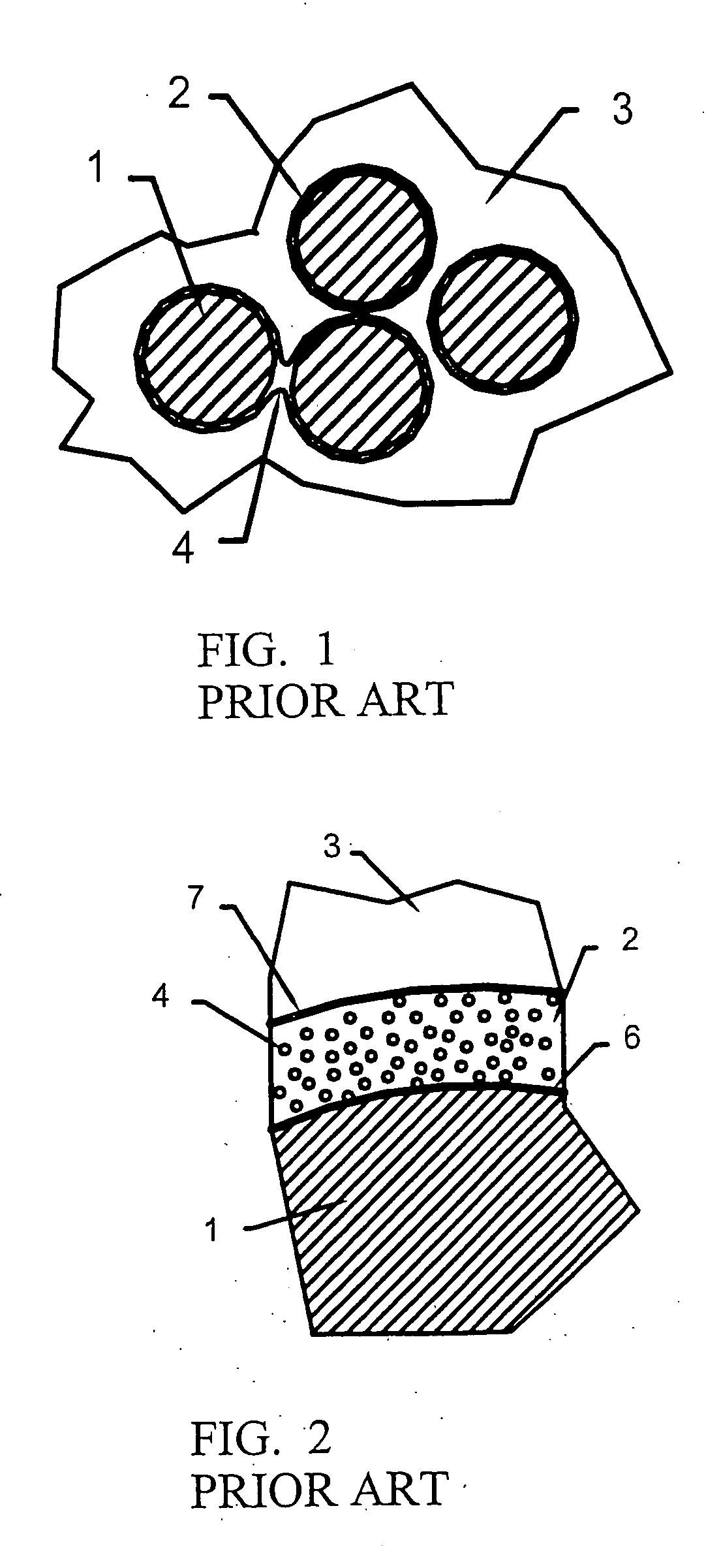
Ceramic-forming polymer material
a ceramic and polymer technology, applied in the direction of pretreatment surfaces, silicon organic compounds, organic compounds of the group 4/14 elements, etc., can solve the problems of high cost, limited material choice, and the design of the coating itself to be much less strong than either fiber or matrix,
- Summary
- Abstract
- Description
- Claims
- Application Information
AI Technical Summary
Problems solved by technology
Method used
Image

Examples
example 1
Coating Polyacronitrile-Based Carbon Fibers
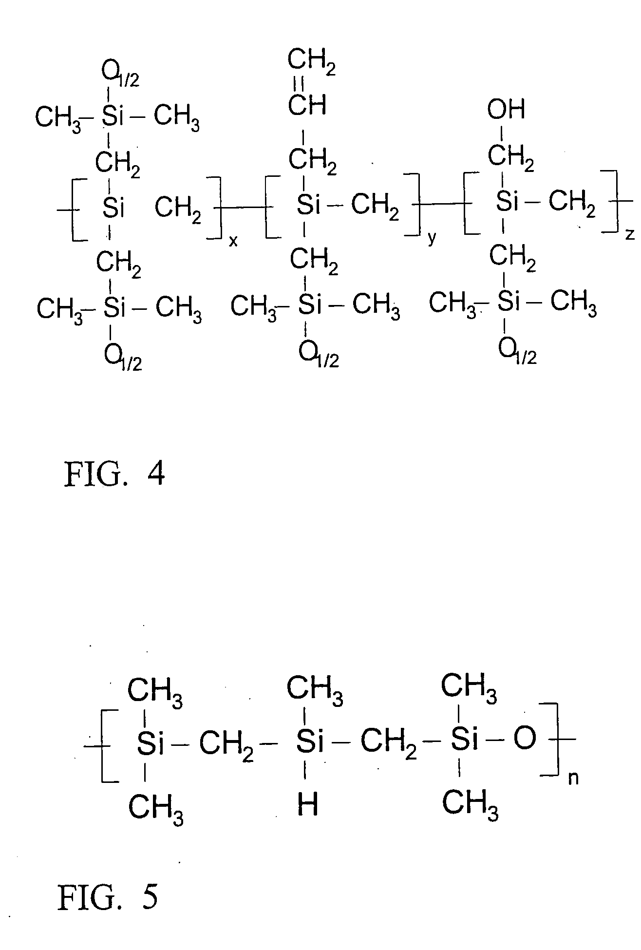
[0053] A 50 gram polyacronitrile (PAN) based carbon fiber disk preform is heat treated by heating in inert gas to 1600° C.-1800° C. for 2 hours. An amount of oxycarbide such as Starfire System's silicon oxycarbide SOC-A35 (FIG. 6) may be used for the ceramic coating. As an alternative, other silicon oxycarbide such as those shown in FIGS. 4 and 5 may be used. In any case, an amount of polymer roughly equal to 18%-22% of the mass of the preform is weighed out on, for example, a three-place analytical balance. An amount of ethyl alcohol, or toluene roughly equal to 150% to 200% of the mass of the preform is weighed out. The polymer is dissolved in the solvent by, for example, stirring in a beaker or flask using a magnetic driven stirrer driving a polytetrafluoroethylene (PTFE) coated stir bar. The polymer is slowly added to the solvent while stirring until all is added. The solution is stirred until all of the polymer is dissolved and the so...
example 2
Coating Near-stoichiometric Silicon Carbide Fibers
[0054] A square foot of cloth composed of near-stoichiometric silicon carbide fiber such as Sylramic, or Tyranno SA, or Hi-Nicalon type-S is first desized (the organic coating needed to allow weaving the fibers) by heating to 350-500° C. in air for about 4 hours or to 850° C. in inert gas for about one to two hours. An amount of oxycarbide forming polymer such as Starfire System's QS-15-017 (FIG. 5), QS-15-003 (FIG. 4) or carbon rich polycarbosilane ceramic forming polymer roughly equal to 8-11% of the mass of the cloth is weighed out on a three-place analytical balance. An amount of hexane, or tetrahydrofuran approximately equal to 100% 150% of the mass of the cloth is weighed out. The polymer is dissolved in the solvent by stirring in a beaker or flask using a magnetic driven stirrer driving a PTFE-coated stir bar. The polymer is slowly added to the solvent while stirring until all is added. The solution is stirred until all of th...
example 3
Coating Silicon Oxycarbide (Si—C—O) or Carbon-rich Silicon Carbide Fibers
[0055] A 50 gram woven preform composed of Hi-Nicalon, Ceramic Grade Nicalon, Tyranno LOX-M, Tyranno LOX-E or ZMI fiber is first desized by heating to 350-500° C. in air for about four hours or to 850° C. in inert gas for about one to two hours. An amount of SOC such as the polymers in FIG. 4 or 5 roughly equal to 8-25% of the mass of the preform is weighed out on a three-place analytical balance. An amount of toluene solvent roughly equal to 75%-150% of the mass of the preform is weighed out. The polymer is dissolved in the solvent by stirring in a beaker or flask using a magnetic driven stirrer driving a PTFE-coated stir bar. The polymer is slowly added to the solvent while stirring until all is added. The solution is stirred until all the polymer is dissolved and the solution becomes clear, e.g., approximately 15 minutes to 1 hour. The preform is placed in an aluminum foil boat and the polymer solution is t...
PUM
| Property | Measurement | Unit |
|---|---|---|
| temperature | aaaaa | aaaaa |
| temperature | aaaaa | aaaaa |
| temperature | aaaaa | aaaaa |
Abstract
Description
Claims
Application Information