Hybrid catalyst system for exhaust emissions reduction

a hybrid catalyst and exhaust technology, applied in the direction of machines/engines, mechanical equipment, separation processes, etc., can solve the problems of exhaust being too oxygen-rich for three-way catalysts to be effective, putting considerable effort toward meeting, and nox from internal combustion engines, etc., to improve the efficiency of the regeneration cycle, reduce nox during regeneration, and enhance conversion

Inactive Publication Date: 2006-01-19
INT ENGINE INTPROP CO LLC
View PDF45 Cites 191 Cited by
  • Summary
  • Abstract
  • Description
  • Claims
  • Application Information

AI Technical Summary

Benefits of technology

[0011] One aspect of the invention relates an exhaust treatment system having an SCR reactor downstream of an NOx adsorber in which syn gas from a fuel reformer is used to regenerate the NOx adsorber. Preferably, the NOx adsorber has a catalyst and functions to reduce NOx during regeneration. Syn gas from a fuel reformer improves the efficiency of the regeneration cycle as compared to injecting fuel directly into the exhaust system. The SCR reactor further enhances conversion by capturing ammonia produced during regeneration and using the ammonia to reduce NOx during lean operation.
[0012] Another aspect of the invention relates to an exhaust treatment system having an SCR reactor downstream of an LNT and an ammonia source separate from the LNT. An LNT will produce some ammonia, but a separate ammonia source can simplify achieving high NOx conversions. The ammonia demand is considerably less than in a pure SCR system and the control system can be simplified by targeting conversion of less than all the NOx escaping the LNT. In one embodiment, the ammonia source comprises an ammonia plant that produces ammonia from a reaction between NOx extracted from a partial exhaust stream and syn gas obtained from a fuel reformer.
[0013] A further aspect of the invention relates to an exhaust system comprising first and second LNTs and one or more valves for selectively directing the exhaust into one or the other LNT. The system further comprises one or more SCRs downstream of the LNTs. This system can be used to reduce the fuel penalty associated with regeneration and allows the LNTs to be regenerated with higher reductant concentrations and longer residence times. In a preferred embodiment, the exhaust streams of the LNTs are unified and lead to an oxidation catalyst. This arrangement allows excess reductants to be oxidized without having to inject air or another oxygen source into the exhaust.
[0014] A still further aspect of the invention relates to a device that can be used to implement the foregoing. The device comprises first and second NOx adsorbers contained in a single housing and one or more valves for selectively directing the exhaust into one or the other adsorber. The one or more valves can be a simple damper. This aspect of the invention provides a simple, compact, and economic method of implementing dual adsorber-based exhaust treatment systems. Another aspect of the invention relates to coating a moving part in an exhaust system with an oxidation catalyst to mitigate fouling.
[0015] Additional aspects of the invention relate to control of LNT / SCR exhaust treatment systems. According to one of these aspects, an ammonia concentration between an LNT and an SCR reactor is measured and used to determine when to terminate a regeneration cycle. Another of these aspect relates to maintaining an estimate of an amount of ammonia adsorbed in the SCR reactor and selectively initiating regeneration of the LNT based on the estimate, whereby regeneration can begin before the ammonia in the LNT is exhausted. This can reduce or prevent NOx breakthrough during the regeneration cycle. A related aspects of the invention involves selectively initiating regeneration based on an NOx concentration measured between an LNT and an SCR reactor. A further aspect of the invention relates to beginning regeneration based on an estimate of the amount of NOx adsorbed in the LNT. In one embodiment, the regeneration cycle is initiated at a point where the LNT is substantially below its NOx storage capacity, whereby the fraction of NOx converted to ammonia during regeneration is substantially greater than it would be if regeneration were postponed until the LNT was closer to saturation. A still further aspect of the invention relates to providing feedback control over the rate at which reductant is supplied during regeneration. The reductant supply rate can be maximized to reduce regeneration time, reduce the fuel penalty, and increase ammonia production subject to limits on the amount of reductant allowed to escape the LNT.

Problems solved by technology

NOx emissions from vehicles with internal combustion engines are an environmental problem recognized worldwide.
Manufacturers and researchers have put considerable effort toward meeting those regulations.
In diesel powered vehicles and vehicles with lean-burn gasoline engines, however, the exhaust is too oxygen-rich for three-way catalysts to be effective.
These techniques alone, however, will not eliminate NOx emissions.
Reduction of NOx in an oxidizing atmosphere is difficult.
It has proved challenging to find a lean-burn NOx catalyst that has the required activity, durability, and operating temperature range.
Lean-burn NOx catalysts also tend to be hydrothermally unstable.
A noticeable loss of activity occurs after relatively little use.
The introduction of a reductant, such as diesel fuel, into the exhaust is generally required and introduces a fuel economy penalty of 3% or more.
Currently, peak NOx conversion efficiency with lean-burn catalysts is unacceptably low.
SCR can achieve NOx reductions in excess of 90%, however, there is concern over the lack of infrastructure for distributing ammonia or a suitable precursor.

Method used


Image

  • Hybrid catalyst system for exhaust emissions reduction
  • Hybrid catalyst system for exhaust emissions reduction
  • Hybrid catalyst system for exhaust emissions reduction

Examples


Embodiment Construction

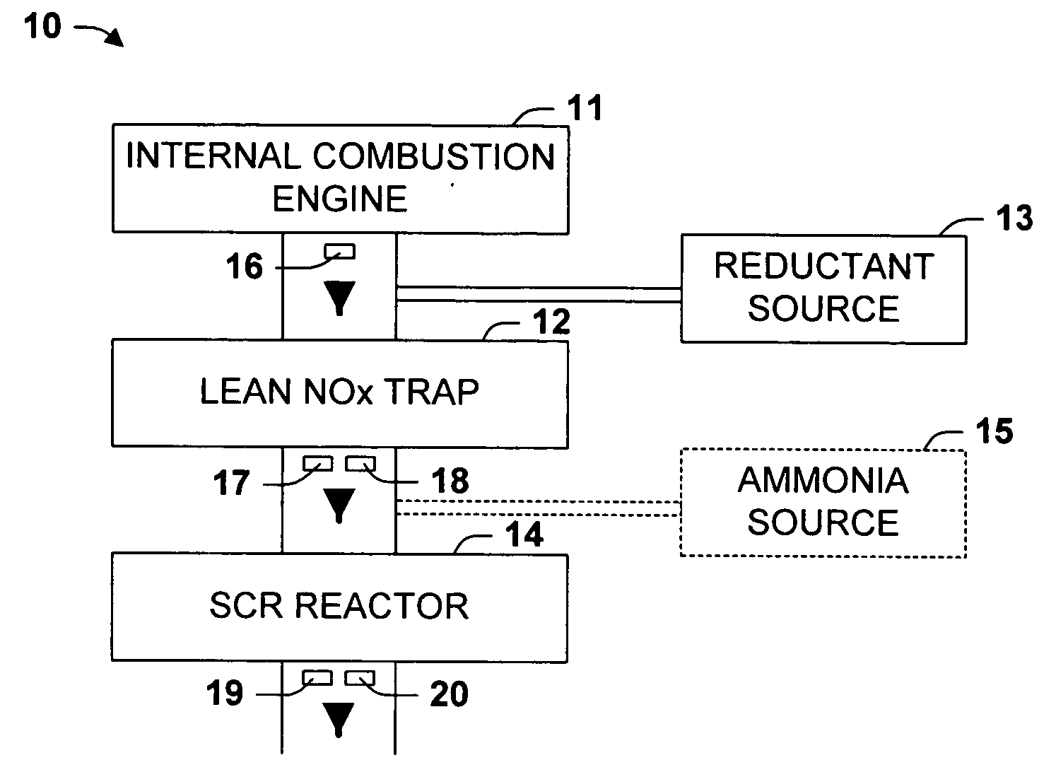
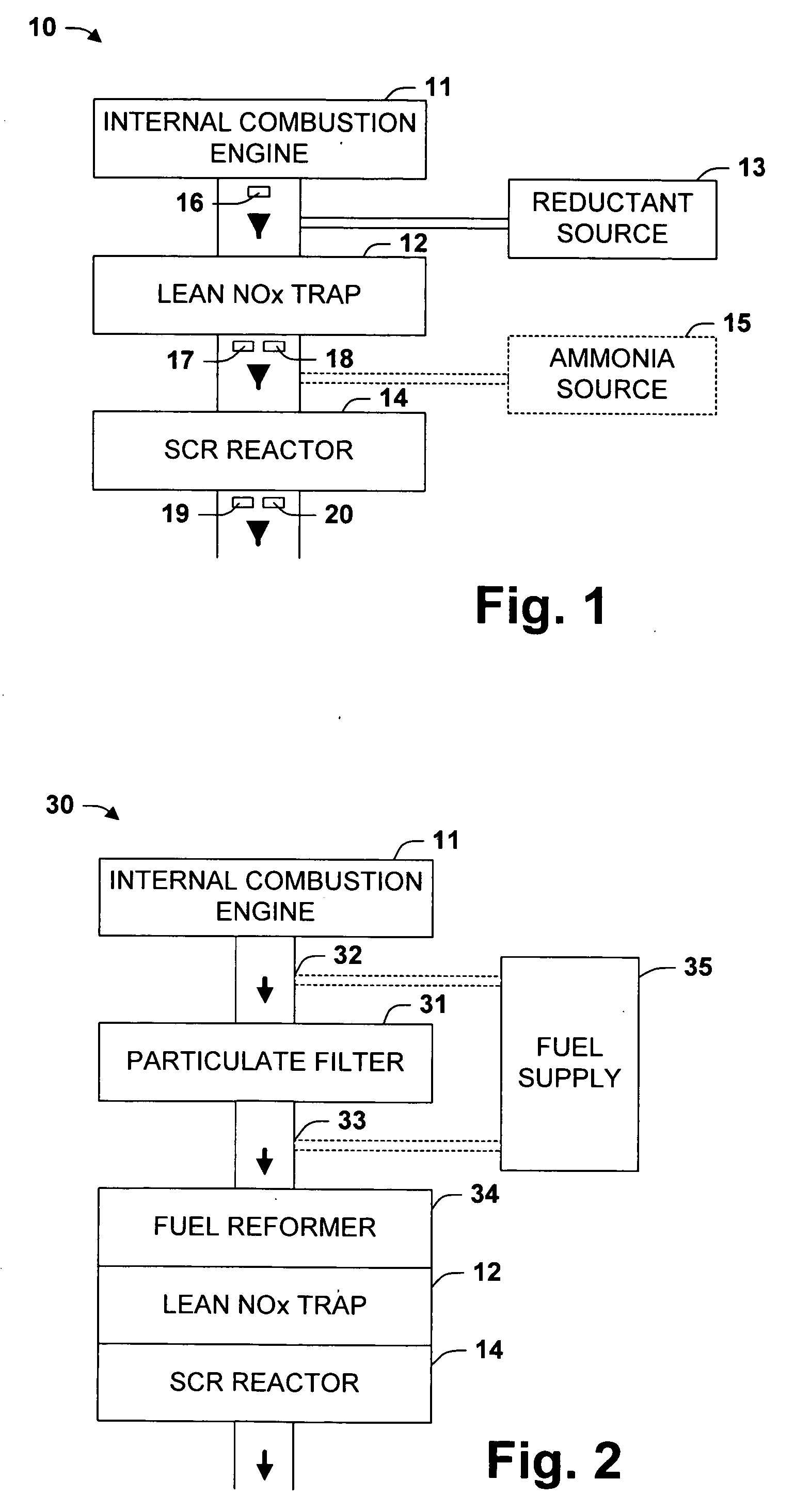
[0022]FIG. 1 is a schematic illustration of a vehicle 10 provided to aide in the description of several aspects of the present invention. The vehicle 10 includes an internal combustion engine 11, a lean NOx trap (LNT) 12, a selective catalytic reduction (SCR) reactor 14, a reductant source 13, an optional ammonia source 15, and sensors 16-20. The vehicle 10 typically produces lean exhaust. The LNT 12 adsorbs NOx from the lean exhaust. From time to time, the exhaust is made rich by injecting a reductant from the reductant source 13. Rich exhaust causes NOx to desorb from the LNT 12. Some of the NOx escapes the LNT, some is reduced to N2, and some is reduced to NH3.

[0023] NOx escaping from the LNT during regeneration and NOx not adsorbed by the LNT during lean operation passes through to the SCR reactor 14. In the SCR reactor 14, some of this NOx is reduced by reaction with NH3. The NH3 can be NH3 produced in the LNT 12 and / or NH3 supplied from the optional ammonia source 15. The SCR...


PUM

PropertyMeasurementUnit
partial pressureaaaaaaaaaa
temperaturesaaaaaaaaaa

Abstract

One aspect of the invention relates an exhaust treatment system having an SCR reactor following a NOx adsorber. Syn gas is used to regenerate the NOx adsorber. Another aspect relates to an LNT / SCR provided with an ammonia source separate from the LNT. A further aspect relates to a system comprising first and second LNTs and one or more SCRs downstream of the LNTs. A still further aspect relates to a device comprising first and second NOx adsorbers contained in a single housing. Another aspect relates to coating a surface of a moving part in an exhaust system with an oxidation catalyst to mitigate fouling. Additional aspects of the invention relate to strategies for controlling one or more of the time to initiate a regeneration cycle, the time to terminate a regeneration cycle, and the reductant injection rate during regeneration of LNT / SCR exhaust treatment systems.

Description

FIELD OF THE INVENTION [0001] The present invention relates to the field of pollution control devices for internal combustion engines, especially diesel engines and lean burn gasoline engines. BACKGROUND OF THE INVENTION [0002] NOx emissions from vehicles with internal combustion engines are an environmental problem recognized worldwide. Several countries, including the United States, have long had regulations pending that will limit NOx emissions from vehicles. Manufacturers and researchers have put considerable effort toward meeting those regulations. In conventional gasoline powered vehicles that use stoichiometric fuel-air mixtures, three-way catalysts have been shown to control NOx emissions. In diesel powered vehicles and vehicles with lean-burn gasoline engines, however, the exhaust is too oxygen-rich for three-way catalysts to be effective. [0003] Several solutions have been proposed for controlling NOx emissions from diesel powered vehicles and lean-burn gasoline engines. O...

Claims


Application Information

Patent Timeline
Patent Type & Authority Applications(United States)
IPC IPC(8): F01N3/00F01N3/10
CPCB01D53/9418F01N13/011B01D53/9495B01D2251/2062B01D2255/911B01D2258/012F01N3/035F01N3/0814F01N3/0821F01N3/0842F01N3/2066F01N3/2073F01N2240/25F01N2240/30F01N2570/18F01N2610/02F01N2610/03Y02T10/24F01N13/0097F01N13/009B01D53/9481Y02A50/20Y02T10/12
Inventor HU, HAORANSTOVER, THOMAS
Owner INT ENGINE INTPROP CO LLC
Why Eureka
Try Eureka