Color organic EL display and method for manufacturing the same

a technology of organic el and display, applied in the direction of discharge tube luminescnet screen, discharge tube/lamp details, incadescent envelope/vessel, etc., can solve the problems of deterioration of gas barrier characteristics, low production efficiency, and poor productivity, so as to improve the step coverage of the gas barrier layer, the effect of improving the coating performance and reducing the number of pin holes

Inactive Publication Date: 2006-01-26
DENSO CORP
View PDF8 Cites 32 Cited by
  • Summary
  • Abstract
  • Description
  • Claims
  • Application Information

AI Technical Summary

Benefits of technology

[0018] In the display, the amount of gas discharged from the substrate and the color filter layer is reduced. Further, the color filter layer is not deteriorated with time. Therefore, the gas barrier layer can be formed appropriately. Further, the gas barrier layer is formed by the atomic layer deposition method, which is superior in coating performance and ...

Problems solved by technology

These difficulties are caused by water contents and the like, which are volatilized from the color filter layer and the overcoat layer, which are made of resin.
However, pin-holes are not considered in view of gas barrier characteristics, as to these conventional gas barrier layers, so that dark spots are easily produced in pixels, and such pixels which cannot maintain desirable light emitting characteristics of organic EL elements are readily produced.
However, the pin-hole measures described in the above documents own problem...

Method used


Image

  • Color organic EL display and method for manufacturing the same
  • Color organic EL display and method for manufacturing the same
  • Color organic EL display and method for manufacturing the same

Examples


first embodiment

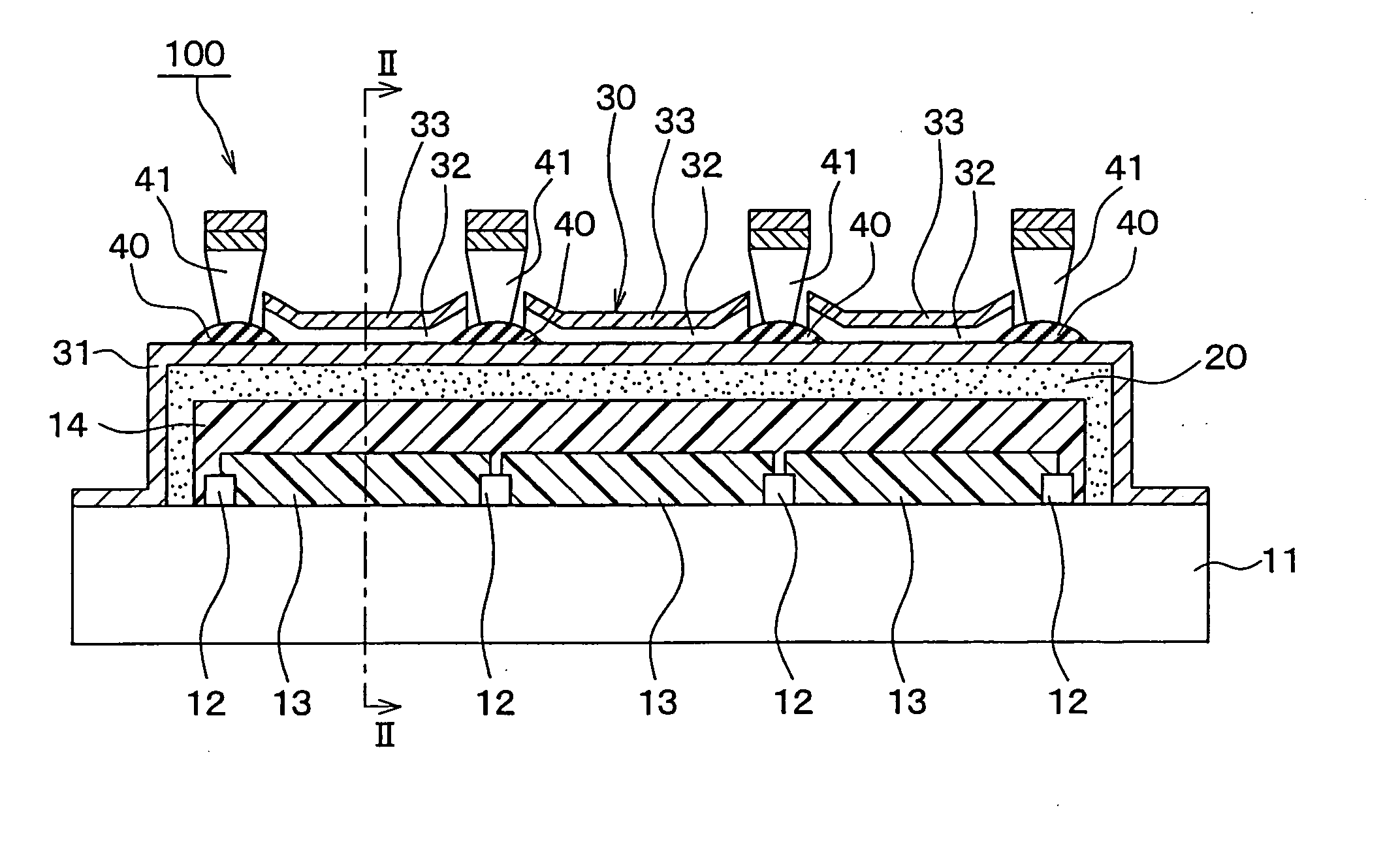
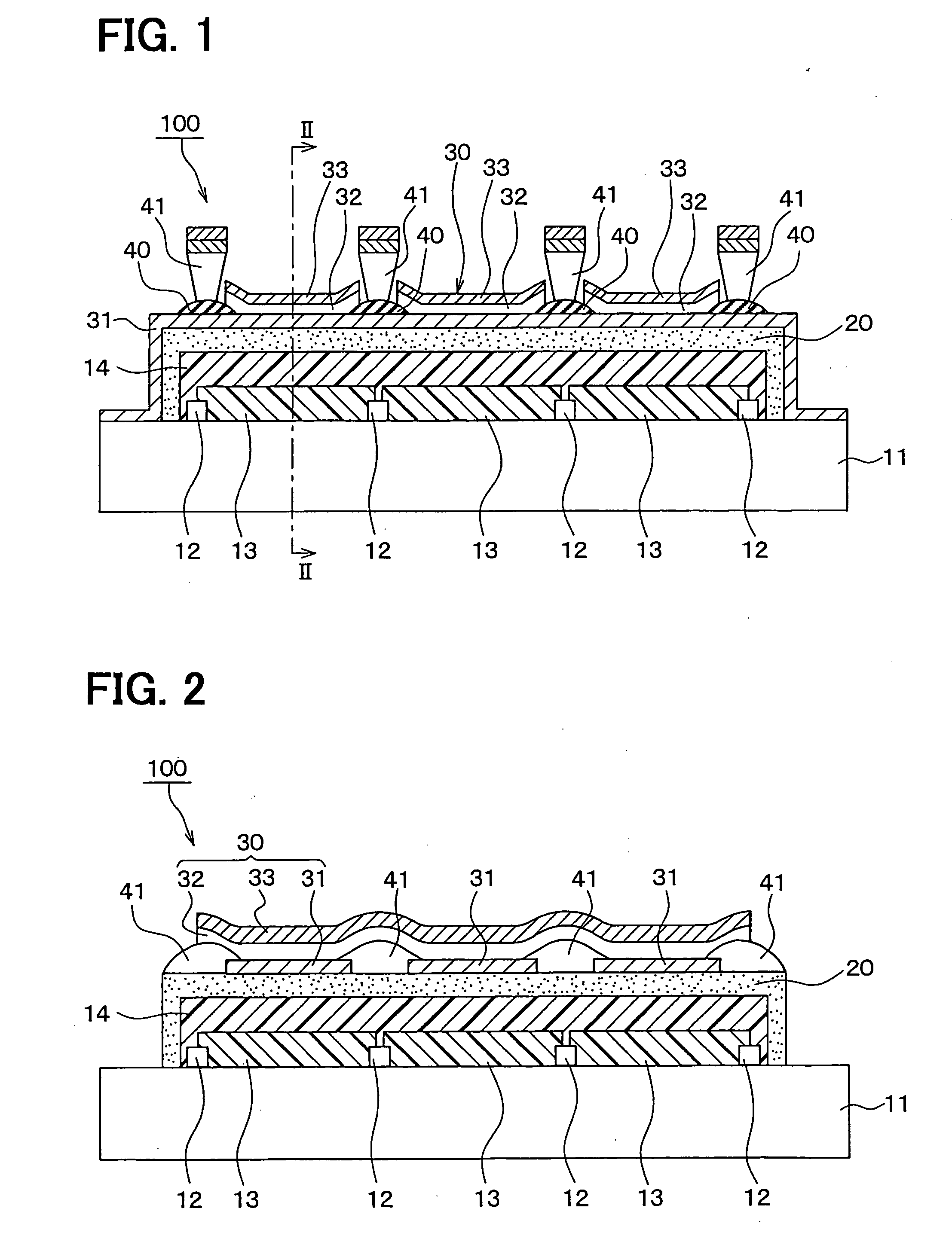
[0045]FIG. 1 is a diagram for indicating a substantially sectional structure of a color organic EL display 100 according to a first embodiment mode of the present invention. FIG. 2 is a diagram for showing a substantially sectional structure of the color organic EL display 100, taken along a dot and dash line II-II shown in FIG. 1.

[0046] [Structure]

[0047] A substrate 11 is made of a glass substrate, a substrate made of a resin (resin substrate), or the like. In this color organic EL display 100 of the first embodiment mode, the substrate 11 corresponds to a transparent substrate 11 which is made of a glass substrate.

[0048] Red, blue, and green color filter layers 13 which correspond to three primary colors of light have been provided on one plane of this glass substrate 11. It should be noted that shadow masks (black matrix) 12 used to separate the color filter layers 13 have been formed on one plane of the substrate 11, and the color filter layers 13 have been provided with the s...

second embodiment

[0159]FIG. 4 is a diagram for indicating a substantially sectional structure of a color organic EL display 200 according to a second embodiment mode of the present invention.

[0160] In this color organic EL display 200, in such a case that the anode 31 has been formed on the gas barrier layer 20 and functions as a transparent conducting film which constitutes the organic EL structural body 30, it is preferable that an SiO2 layer 50 capable of improving a close contacting characteristic between these gas barrier layer 20 and transparent conducting film 31 is interposed between the gas barrier layer 20 and the transparent conducting film 31.

[0161] This SiO2 layer 50 may be formed by performing a sputtering method, or the like, and a film thickness thereof may be selected to be, for example, approximately 20 nm. Since the close contacting characteristic between the gas barrier layer 20 and the transparent conducting film 31 can be improved by this SiO2 layer 50, there is a merit that ...

third embodiment

[0162]FIG. 5 is a diagram for indicating a substantially sectional structure of a color organic EL display 300 functioning as an organic electronic device element according to a third embodiment mode of the present invention.

[0163] Also, the substrate 11 is constituted by a glass substrate, a substrate made of a resin (namely, resin substrate), or the like. The substrate 11 corresponds to such a transparent substrate 11 which is made of non-alkali glass and does not contain such an alkaline component as potassium and sodium.

[0164] Similar to the above-explained embodiment mode, the shadow mask (black matrix) 12 and the color filter layers 13 have been formed on one plane of this substrate 11, on which the transparent overcoat layer 14 has been formed as a fattening layer.

[0165] Then, the gas barrier layer 20 has been formed on the overcoat layer 14 in such a manner that this gas barrier layer 20 covers the overcoat layer 14 by executing an atomic layer growing method at a tempera...


PUM


Abstract

A color organic EL display includes: a substrate; a color filter layer disposed on the substrate; a gas barrier layer disposed on the color filter layer; and an organic EL structural body disposed on the gas barrier layer. The substrate and the color filter layer provide an underlayer of the gas barrier layer. The underlayer is a degassed underlayer. The gas barrier layer is provided by an atomic layer deposition method at a temperature equal to or lower than a decomposition starting temperature of the color filter layer.

Description

CROSS REFERENCE TO RELATED APPLICATIONS [0001] This application is based on Japanese Patent Applications No. 2004-211593 filed on Jul. 20, 2004, No. 2005-35891 filed on Feb. 14, 2005, and No. 2005-157722 filed on May 30, 2005, the disclosures of which are incorporated herein by references. FIELD OF THE INVENTION [0002] The present invention relates to a color organic EL display and a method for manufacturing a color organic EL display. BACKGROUND OF THE INVENTION [0003] A color organic EL (i.e., electroluminescence) display constituted by interposing a gas barrier layer between an organic EL (electroluminescence) structural body and a color filter is well-known. [0004] This sort of color organic EL display is equipped with such a structure that a color filter layer, a gas barrier layer, and an organic EL structural body have been successively stacked on a substrate. [0005] Specifically, when an organic EL structural body for emitting white light is combined with a color filter, the ...

Claims


Application Information

Patent Timeline
IPC IPC(8): H05B33/00
CPCH01L51/5237H01L27/322H10K59/38H10K59/8731H05B33/22H05B33/10H10K50/8445
Inventor ISHIDA, TAIZOMORI, KAHORUMIYAJI, SHIGERUKAWAI, SHOICHITERA, RYONOSUKEINO, KOJI
Owner DENSO CORP
Why Eureka
Try Eureka