Copper fluoride based nanocomposites as electrode materials
a technology of copper fluoride and nanocomposites, which is applied in the direction of electrochemical generators, cell components, transportation and packaging, etc., can solve the problems of reducing the final acceptability of rechargeable cells, affecting the performance of rechargeable cells, and reducing the specific capacity of rechargeable cells, etc., to achieve high recharge and/or discharge rates. , the effect of high specific capacity
- Summary
- Abstract
- Description
- Claims
- Application Information
AI Technical Summary
Benefits of technology
Problems solved by technology
Method used
Image
Examples
example 1
Electrode Preparation
[0079] Electrodes were prepared by adding poly-vinylidene fluoride-co-hexafluoropropylene (Kynar 280, Elf Atochem), carbon black (Super P, MMM), and dibutyl phthalate (Aldrich) to the inventive nanocomposites in acetone. The slurry was tape cast, dried for 1 hour at 22° C., and rinsed in 99.8% anhydrous ether (Aldrich) to extract the dibutyl phthalate plasticizer. The electrodes, 1 cm2 disks or coin cells typically containing 57±1% inventive nanocomposites and 12±1% carbon black, were tested electrochemically versus Li metal (Johnson Matthey). The Swagelok™ or coin cells were assembled in a Helium-filled dry box using Whatman GF / D glass fiber separators saturated with 1 M LiPF6 in ethylene carbonate:dimethyl carbonate (EC:DMC 1:1 in vol.) electrolyte (Merck). The cells were controlled by Mac-Pile (Biologic) or Maccor battery cycling systems. Cells were cycled under a constant current of 22 mA / g at 24° C.
example 2
Preparation of CuF2 Nanocomposite with MoO3 Matrix and CuF2 Non-Nanocomposite Reference Material
[0080] A sample of 93% weight CuF2, 15% weight carbon and 7% weight MoO3 were milled in a high-energy impact mill under a helium atmosphere for 20 min. and subsequently annealed at 200° C. before the sample was extracted for structural and electrochemical characterization. The inventive nanocomposite was composed of crystallites of approximately 30 nm. As a basis for comparison, CuF2 was thoroughly mixed under low-energy shear grinding condition using a mortar and pestle to yield a reference electrode material composed of particles with a size of about 1000 nm.
example 3
Specific Capacities of CuF2 Inventive Nanocomposite and the CuF2 Non-Nanocomposite Reference Material
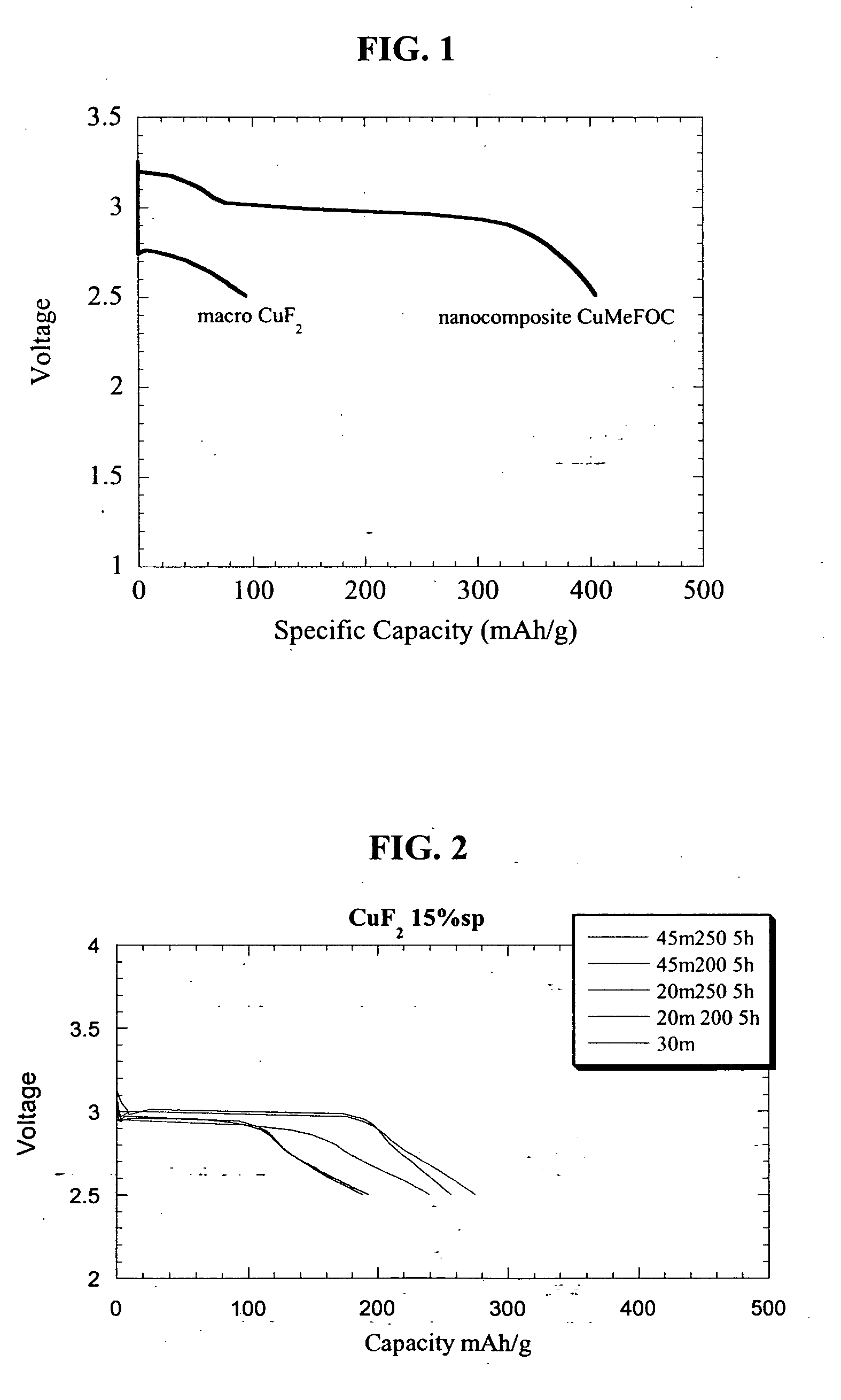
[0081] Both the inventive nanocomposite and the reference electrode material were compared to assess their electrochemical efficacy as electrode materials. A series of cells was fabricated in the above-described manner and tested at room temperature (22° C.) over a period of time at constant amperage cycles of 22 mA / g between 4.5 and 2.0 V. The substantially insignificant specific capacity of about 100 mAh / g for the reference electrode material mixture may be seen in FIG. 1 which specific capacities for a non-nanocomposite CuF2 and a copper fluoride nanocomposite. As seen in the figure, results of similar testing for the inventive nanocomposite show that the specific capacity of the milled copper fluoride increased by 400 % compared with the reference electrode.
PUM
 Abstract
Description
Claims
Application Information
 - R&D
- Intellectual Property
- Life Sciences
- Materials
- Tech Scout
- Unparalleled Data Quality
- Higher Quality Content
- 60% Fewer Hallucinations
Browse by: Latest US Patents, China's latest patents, Technical Efficacy Thesaurus, Application Domain, Technology Topic, Popular Technical Reports.
© 2025 PatSnap. All rights reserved.Legal|Privacy policy|Modern Slavery Act Transparency Statement|Sitemap|About US| Contact US: help@patsnap.com


