Method of manufacturing liquid discharge head and method of manufacturing substrate for liquid discharge head

a technology of liquid discharge head and liquid discharge substrate, which is applied in the direction of magnetic recording, data recording, instruments, etc., can solve the problems of difficult production of ink jet recording head with nozzle, etc., and achieve high yield factor, high application value, and high density

Inactive Publication Date: 2006-02-09
CANON KK
View PDF39 Cites 20 Cited by
  • Summary
  • Abstract
  • Description
  • Claims
  • Application Information

AI Technical Summary

Benefits of technology

[0016] As aforementioned, according to the present invention, a piezoelectric element drive type ink jet recording head, which give rise to a good yield factor and is highly dense, will become obtainable. This can provide with an ink jet recording head which is highly applicable to various types of inks and enables printing with high quality.

Problems solved by technology

Therefore, it was difficult to produce an ink jet recording head with nozzles disposed with high fineness.

Method used


Image

  • Method of manufacturing liquid discharge head and method of manufacturing substrate for liquid discharge head
  • Method of manufacturing liquid discharge head and method of manufacturing substrate for liquid discharge head
  • Method of manufacturing liquid discharge head and method of manufacturing substrate for liquid discharge head

Examples


example 1

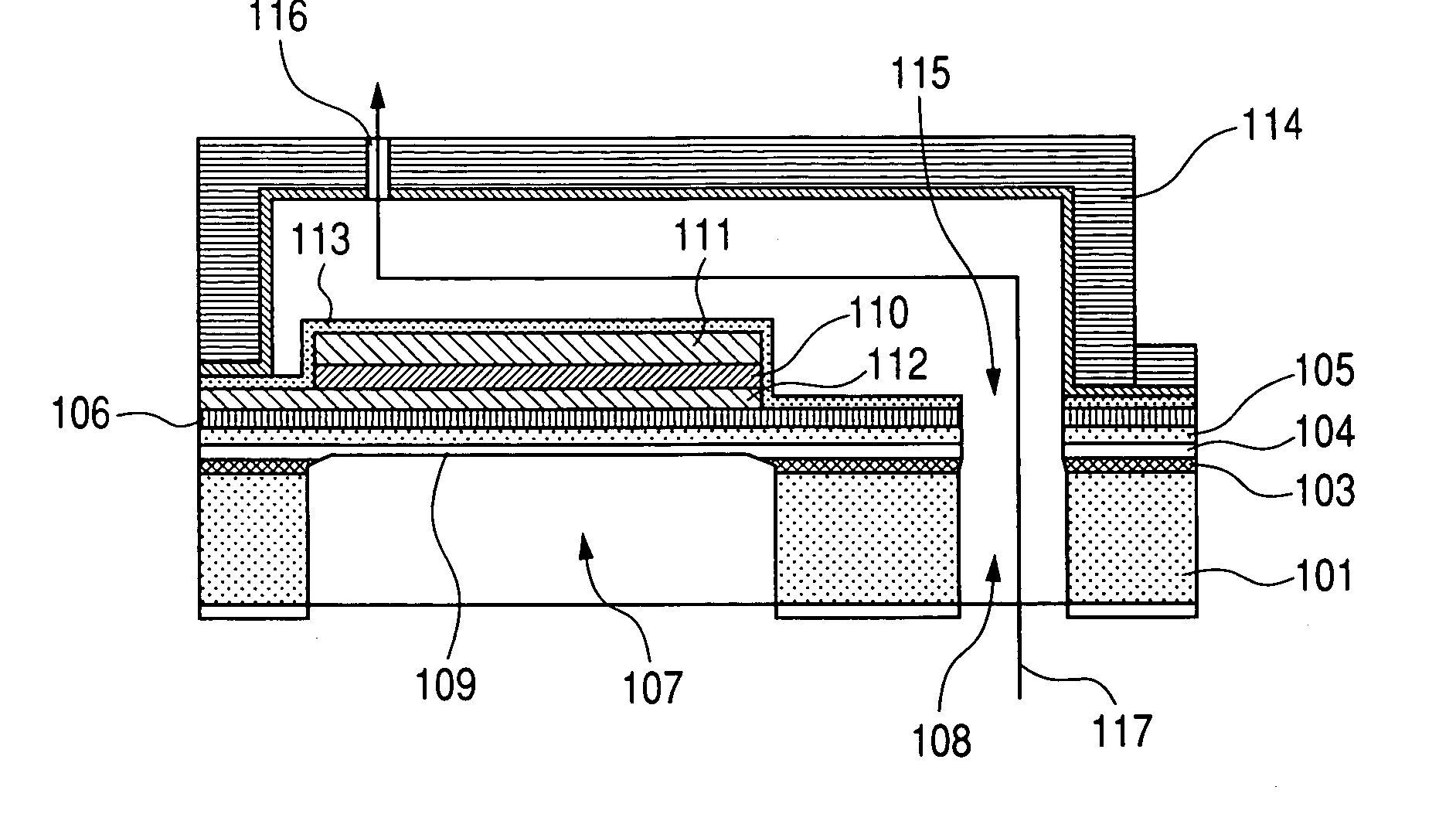
[0094]FIG. 1 is a sectional schematic diagram of an ink jet recording head showing an example of the present invention. An Si substrate 101 with thickness 635 μm and with the plane orientation (110) was used as a substrate.

[0095] On an Si substrate 101, 300 nm Si3N4 film 103 was formed with LPCVD, 200 nm SiO2 film 104 was formed with CVD and 2 μm of Si single crystal layer 105 by lamination and polishing; 10 nm of YSZ film was deposited as a buffer layer 105 with sputtering; 2 μm of single crystal lead zirconate titanate (PZT) 110 was deposited with sputtering; and 10 / 150 nm of Ti / Pt was deposited as the upper electrode 111; and thereabove 100 nm of SiO2 being the protection film 113 was deposited.

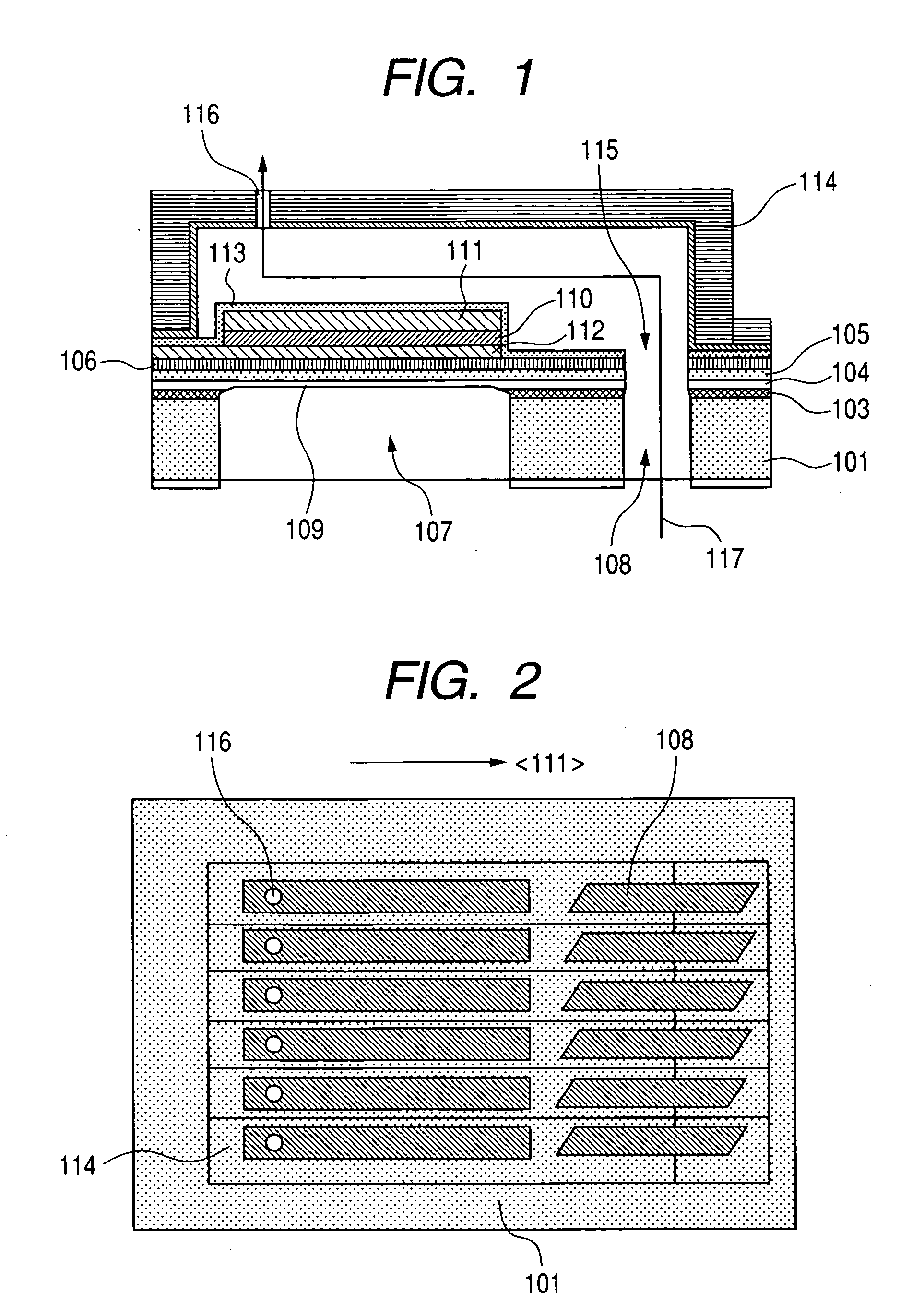
[0096] In the silicon substrate, in order to form a space behind the vibration plate 109, a hole 107 to become a vibration plate back space 107 and a hole to become an ink supply orifice 108 from the rear plane were formed with anisotropy etching.

[0097] On the substrate, individual pres...

example 2

[0102] With FIG. 9, a second example of the present invention will be described.

[0103] In contrast with the first example where the vibration plate is formed under the piezoelectric element, in a second example, the vibration plate is formed on the piezoelectric element.

[0104] As the configuring elements, the Si vibration plate in Example 1 undergoes etching, a Pt electrode and YSZ are disposed under the piezoelectric element 208, and a 2 μm SiNx film, which is deposited with plasma CVD, is disposed on the piezoelectric element and functions as a vibration plate 209.

[0105] Using this head, a high quality printed product without lack in discharge was obtained by an ink of coefficient of viscosity 3 cp containing toluene as the main component at 15 KHz and with droplets of 3 pl and 12.5 mm width.

example 3

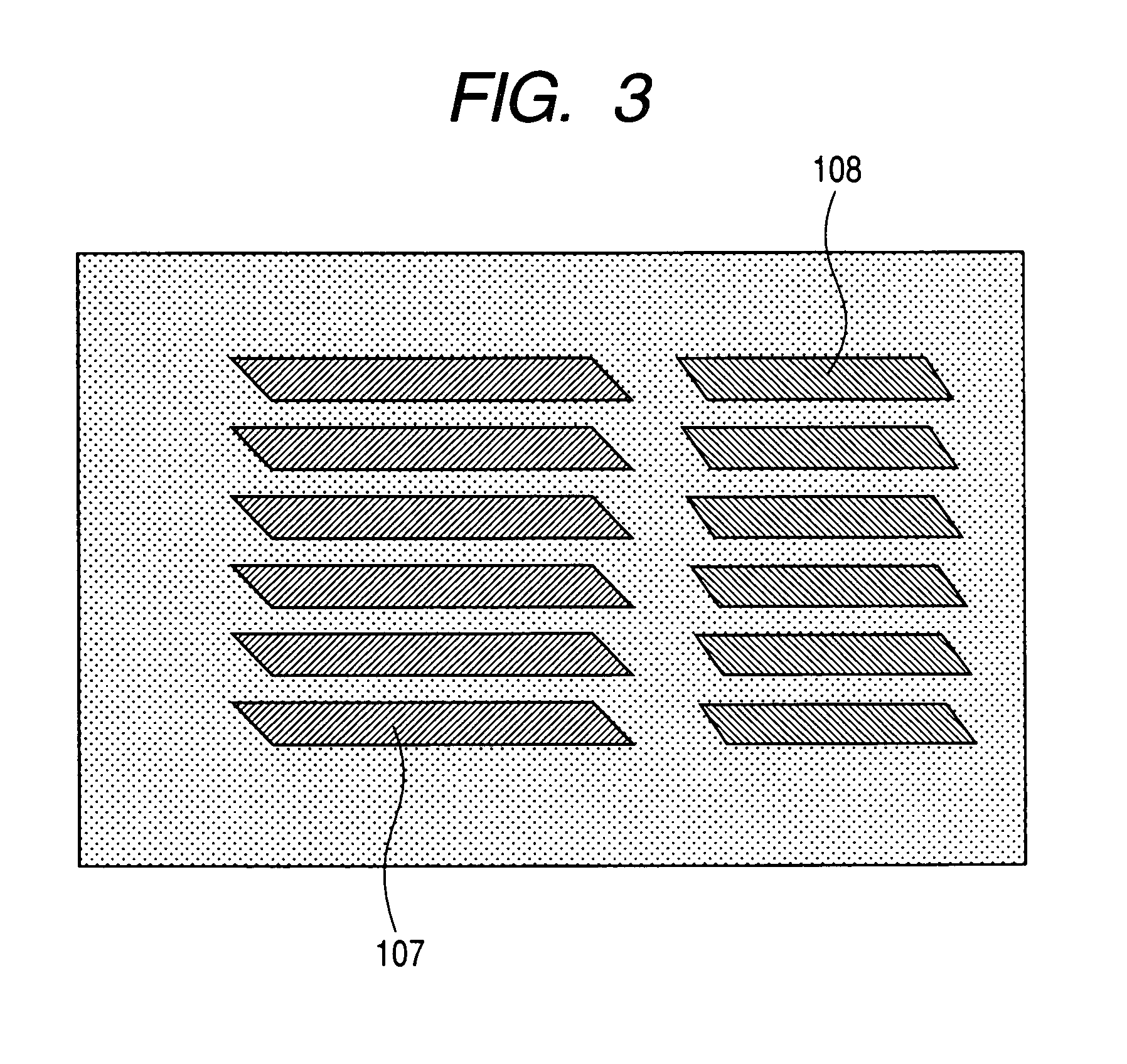
[0106] An example of the process of an ink jet recording head by the present example will be described sequentially with FIG. 4A to FIG. 4E. [0107] (1) In the silicon substrate 101 of the outer diameter 150 mm, the thickness of 630 μm and the substrate plane orientation (110), with a high density plasma etching apparatus (ICP), as in FIG. 8 viewed from the top, parallelogram-shaped concave part (a location corresponding with the space 107 behind the vibration plate) with each line to be in parallel to the plane equivalent to the (111) plane and with longer lines of 3 mm length and shorter lines of 70 μm length, making the narrow angle of 70.5 degrees as in FIG. 8 viewed from the top and parallelogram-shaped concave (a location corresponding with the ink supply orifice 108) with longer lines of 500 μm length and shorter lines of 70 μm length were formed. [0108] (2) Onto at least the plane where the parallelogram-shaped concave part has been formed in the silicon substrate 101, poly s...


PUM


Abstract

A method of manufacturing a liquid discharge head including a pressure generating chamber communicated to a discharge port for discharging liquid and a piezoelectric element which is provided corresponding with the pressure generating chamber and includes a piezoelectric material film and a pair of electrode films sandwiching the piezoelectric material film, including: a step of preparing a structure with a single crystal Si layer being accumulated above a front surface of an Si substrate through an etching stop layer; a step of forming a buffer layer on the above described single crystal Si layer; a step of forming, above the above described buffer layer, the above described piezoelectric material film consisting of a single crystal thin film or a thin film which is directed in a preferential orientation to a direction of the polarization through one of the above described pair of electrode films; a step of forming the above described pressure generating chamber on the above described piezoelectric material film; and a step of etching a location corresponding with the above described piezoelectric material film of the above described Si substrate from a rear surface of the above described Si substrate to reach the above described etching stop layer.

Description

BACKGROUND OF THE INVENTION [0001] 1. Field of the Invention [0002] The present invention relates to a method of manufacturing a liquid discharge head (hereinafter, also referred to as “ink jet recording head), which discharges liquid by applying energy to liquid from outside and a method of manufacturing a substrate for a liquid discharge head. [0003] 2. Related Background Art [0004] Printers with ink jet recording heads as printing apparatuses have become to be widely used due to their good printing performance and low costs. Ink-jet recording heads such as the one which generates bubbles in ink with thermal energy to discharge ink droplets with pressure waves by those bubbles and the one which has used pressure waves by vibrators such as a piezoelectric element, etc. have been developed. [0005] Among the above described ink jet recording heads, the one which has used piezoelectric elements is provided is configured that when a predetermined voltage is applied to an ink flow path ...

Claims


Application Information

Patent Timeline
Patent Type & Authority Applications(United States)
IPC IPC(8): G01D15/00
CPCB41J2/161B41J2/1639B41J2/1626
Inventor TOKUNAGA, HIROYUKI
Owner CANON KK
Why Eureka
Try Eureka