Phosphor and manufacturing method for the same, and light source

a technology of phosphor and manufacturing method, applied in the direction of electroluminescent light source, chemistry apparatus and processes, and can solve the problems of short life span, insufficient light emission on the longer wavelength side of visible light, and inability to obtain white light emission with a slightly reddish white color like an electric bulb, etc., to achieve easy manufacturing, improved emission efficiency, and low manufacturing cost

Active Publication Date: 2006-02-16
CITIZEN ELECTRONICS CO LTD +1
View PDF37 Cites 105 Cited by
  • Summary
  • Abstract
  • Description
  • Claims
  • Application Information

AI Technical Summary

Benefits of technology

[0041] According to the manufacturing method of the phosphor described in any one of the fourteenth to seventeenth aspects, the oxygen in the phosphor composition described in any one of the first to thirteenth aspects is reduced, and the phosphor having an emission spectrum with a peak on the longer wavelength side and having an improved emission efficiency can be easily manufactured at an inexpensive manufacturing cost.
[0042] According to a light emission apparatus described in the eighteenth aspect, the light emission apparatus having a desired emission color, having a high emission intensity and luminance, and having high efficiency can be obtained.

Problems solved by technology

At present, a discharge type fluorescent lamp and an incandescent bulb used as the illumination device involve problems that a harmful substance such as mercury is contained, and life span is short.
However, in the white LED illumination obtained by combining the blue LED and the yellow phosphor (YAG:Ce), the light emission on the longer wavelength side of a visible light becomes insufficient, thus emitting the light with slightly bluish white emission color, and the white light emission with slightly reddish white color like an electric bulb can not be obtained.
In addition, in the white LED illumination obtained by combining the near ultraviolet / ultraviolet LED and the phosphor of R, G, B, and others, the red phosphor out of three color phosphors has a deteriorated excitation efficiency, thereby exhibiting low emission efficiency, compared to other phosphors.
Therefore, the mixing ratio of only red phosphor must be increased and the phosphor for improving luminance becomes thereby insufficient, making it impossible to obtain white color with high luminance.
Further, a problem involved therein is that the aforementioned red phosphor has a sharp emission spectrum, thereby exhibiting deteriorated color rendering property.
However, when it is caused to emit light by using the near ultraviolet / ultraviolet light emitted from the near ultraviolet / ultraviolet LED, the YAG:Ce yellow phosphor is out of the excitation range with high efficiency, and therefore an adequate light emission can not be obtained.
Then, the problem that the excitation range with high efficiency is narrow for the YAG:Ce yellow phosphor involves a situation such that a wavelength balance of blue color and yellow color is lost, because the emission wavelength of the blue LED is out of an optimal excitation range of the YAG:Ce yellow phosphor by the deviation of an emission wavelength caused by the deviation of the light emitting elements during manufacturing the blue LED even in a case of light emission by using the blue light emitted from the aforementioned blue LED.
When the aforementioned situation occurs, the problem involved therein is that a color tone of the white light which is obtained by synthesizing the blue light and the yellow light is changed.
Here, in manufacturing the LED, it is difficult to prevent the deviation of the light emitting elements in the present circumstances.
However, such a phosphor fails in reaching a satisfactory level in the present circumstances.

Method used


Image

  • Phosphor and manufacturing method for the same, and light source
  • Phosphor and manufacturing method for the same, and light source
  • Phosphor and manufacturing method for the same, and light source

Examples


example 1

[0119] Commercially available Ca3N2(3N), AlN(3N), Si3N4(3N), and Eu2O3(3N) were prepared, and each raw material was weighed to obtain 0.985 / 3 mol of Ca3N2, 1.0 mol of AlN, 1 / 3 mol of Si3N4, and 0.015 / 2 mol of Eu2O3, and thereafter was mixed in the glove box under the nitrogen atmosphere by using the mortar. The raw materials thus mixed were put in the crucible and set in the firing furnace, and retained / fired for 3 hours at 1600° C. in the nitrogen atmosphere wherein the pressure is set at 0.05 MPa, with the nitrogen ventilated at 1.0 L / min while maintaining the aforementioned 0.05 MPa pressure. Thereafter, the fired object thus obtained were cooled from 1600° C. to 200° C. for 1 hour, then the phosphor including the product phase expressed by the composition formula Ca0.985AlSiN3:Eu0.0150 was obtained. The particle size of the obtained phosphor sample was 3 to 4 μm by SEM observation. (hereafter, in the examples 2 to 6 also, the particle size of the obtained phosphor was 3 to 4 μm ...

example 2

[0134] The phosphor of an example 2 was obtained in the same way as the example 1, excepting that the mixed raw material was put in the crucible and retained and fired for 3 hours at 1500° C. in the nitrogen atmosphere, and thereafter cooled for 1 hour from 1500° C. to 200° C., to obtain the phosphor containing the product phase expressed by the composition formula Ca0.985AlSiN3:Eu0.0150.

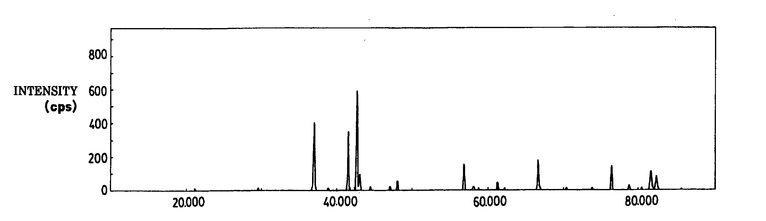
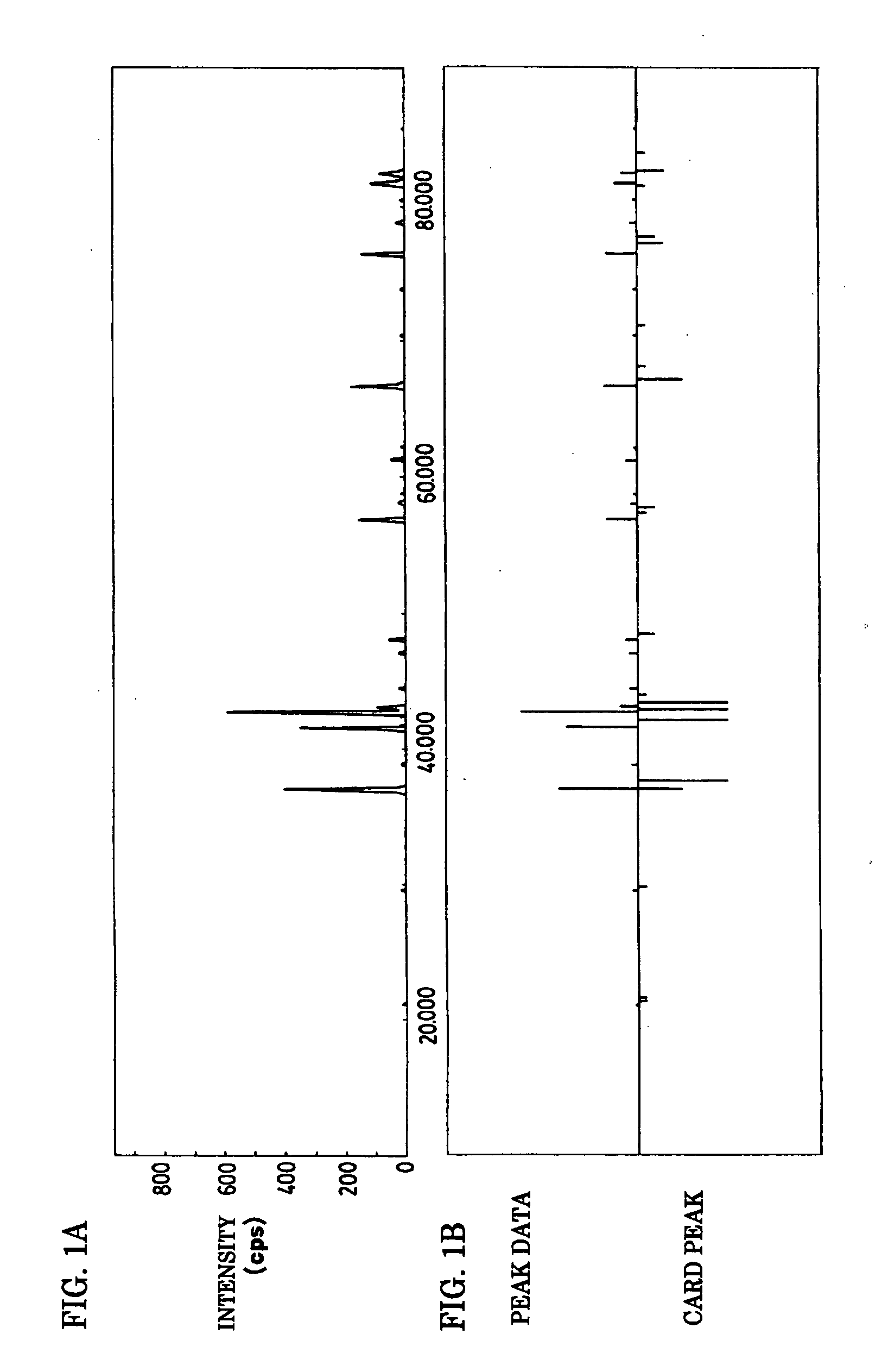
[0135] The measurement result of the oxygen / nitrogen concentrations, the emission characteristic, and the powder characteristic of the phosphor sample are shown in table 1, and the powder X-ray diffraction pattern of the phosphor thus obtained is shown by thick solid line in FIGS. 4A to 4G.

[0136] In FIG. 4, FIG. 4A shows the X-ray diffraction pattern over the entire Bragg angle (2θ) range from 0° to 90°, and FIGS. 4B to 4G are expanded views of characteristic parts of the Bragg angle, wherein FIG. 4B shows the characteristic Bragg angle range from 35° to 40°, FIG. 4C shows the range from 40° to 45...

example 3

[0137] In the mixing ratio of each raw material, the phosphor sample according to the example 3 was manufactured in the same way as the example 2, excepting that Ca3N2 was selected to be (0.985-0.25) / 3 mol and CaO was selected to be 0.25 mol, and the emission characteristic was measured. The measurement result of the oxygen / nitrogen concentrations, the emission characteristic, and the powder characteristic of the phosphor sample are shown in table 1, and the powder X-ray diffraction pattern thus obtained is shown by thin solid line in FIGS. 4A to 4G.


PUM

PropertyMeasurementUnit
aaaaaaaaaa
aaaaaaaaaa
aaaaaaaaaa

Abstract

To provide a phosphor having an emission characteristic such that a peak wavelength of light emission is in a range from 580 to 680 nm, and having a high emission intensity, and having a flat excitation band with high efficiency for excitation light in a broad wavelength range from ultraviolet to visible light (wavelength range from 250 nm to 550 nm). For example, Ca3N2(2N), AlN(3N), Si3N4(3N), Eu2O3(3N) are prepared, and after weighing and mixing a predetermined amount of each raw material, raw materials are fired at 1500° C. for 6 hours, thus obtaining the phosphor including a product phase expressed by a composition formula CaAlSiN3:Eu and having an X-ray diffraction pattern satisfying a predetermined pattern.

Description

TECHNICAL FIELD OF THE INVENTION [0001] The present invention relates to a phosphor used in a display device such as a cathode-ray tube (CRT), a plasma display (PDP), a field emission display (FED), electroluminescence (EL) display, a fluorescent display tube, and an illumination device such as a fluorescent lamp, and a manufacturing method of the same, and a light source using the phosphor. BACKGROUND ART [0002] At present, a discharge type fluorescent lamp and an incandescent bulb used as the illumination device involve problems that a harmful substance such as mercury is contained, and life span is short. However, in recent years, a high luminescence LED emitting light of near ultraviolet / ultraviolet to blue color has been developed in sequence, and the white LED illumination for the practical application of the next generation has been actively studied and developed, by combining the light of ultraviolet to blue color generated from the LED, and a phosphor having an excitation b...

Claims


Application Information

Patent Timeline
Patent Type & Authority Applications(United States)
IPC IPC(8): C09K11/08C09K11/64
CPCC09K11/0883H05B33/14C09K11/7734C09K11/77348C09K11/08C09K11/01
Inventor SAKANE, KENJINAGATOMI, AKIRAGOTOH, MASAHIROYAMASHITA, SHUJI
Owner CITIZEN ELECTRONICS CO LTD
Why Eureka
Try Eureka