Localized plasma processing

a plasma processing and localization technology, applied in the field of plasma processing, can solve the problems of slow processing rate, stop processing surface, gas molecules adhering to the surface area quickly exhausted, etc., and achieve the effect of high processing rate and minimal unintentional damage to the substra

Active Publication Date: 2006-03-02
FEI CO
View PDF10 Cites 56 Cited by
  • Summary
  • Abstract
  • Description
  • Claims
  • Application Information

AI Technical Summary

Benefits of technology

[0012] An object of the invention is to provide a method of localized processing that has a relatively high processing rate and produces minimal unintentional damage to the substrate.
[0013] The invention provides a method and apparatus for localized plasma processing. In some embodiments, the reactive ions contacting the work piece can have very little kinetic energy to minimize or eliminate damage to the substrate surface. The quantity of reactive gas molecules striking the work piece surface in a plasma system of the invention can be much greater than the quantity of reactive gas molecules generated by a charged particle beam, so the deposition and etch rate are much greater than the rates typically achieved by focused charged particle beam systems.
[0014] Because, unlike prior art plasma processing systems, the plasma processing is localized, some embodiments of the invention are suitable for use within a vacuum chamber, without raising the pressure in the vacuum system to unacceptable levels. For example, the localized plasma processing could be performed in a vacuum chamber that includes a focused ion beam system, a scanning electron microscope, or a transmission electron microscope. A work piece can be processed by the invention and then operated upon by a charged particle beam, without the inefficiency of having to open the vacuum chamber and subsequently re-evacuate the chamber.

Problems solved by technology

While the density of charged particles in a focused ion beam can be relatively high, the beam diameter is typically very small, so the total number of particles striking the surface is relatively small, which means a relatively slow processing rate.
Moreover, the high current density in the beam means that gas molecules adhered to the surface area quickly exhausted, and the beam must stop processing the surface until additional gas particles have time to adsorb to the surface.
There are other disadvantages to the use of a focused ion beams for etching and depositing material.
Because of the mass and energy of ions in the beam, the beam will inadvertently cause damage to the surface of the substrate and leave implanted ions within the crystal structure of the substrate.
This can also change the shape of the features on the substrate, so that subsequent measurements do not accurately characterize the features before processing.

Method used


Image

  • Localized plasma processing
  • Localized plasma processing
  • Localized plasma processing

Examples


Embodiment Construction

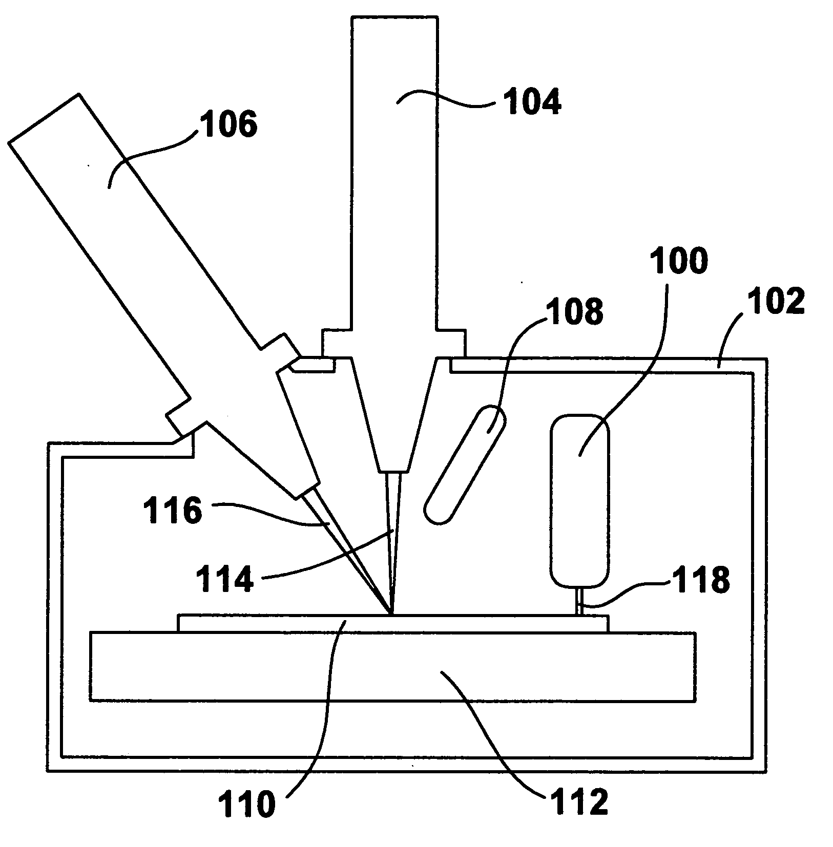
[0018] A preferred embodiment can be used for localized plasma processing for many applications. In some embodiments, the invention can be used for applications that are currently performed using a charged particle system with a gas injection system (GIS). In these embodiments, the invention uses a plasma to activate a reactive gas, rather than using a charged particle beam. A wider variety of gases can be used in the invention than in a conventional GIS system, because in a typical charged particle beam system, the gas must adhere to the surface to be activated by the charged particle beam. The present invention can use almost any gas that is currently used in GIS systems, as well as gases that are currently used in plasma systems for whole wafer processing. Because the jet of reactive gas of the present invention is typically not as focused as a charged particle beam, embodiments of the invention process a larger area.

[0019] Embodiments of the present invention can process areas ...


PUM

PropertyMeasurementUnit
pressureaaaaaaaaaa
energyaaaaaaaaaa
energyaaaaaaaaaa

Abstract

A method of localized plasma processing improves processing speed and reduces work piece damage compared to charged particle beam deposition and etching. In one embodiment, a plasma jet exits a plasma generating chamber and activates a reactive gas. A jet of plasma and reactive gas impacts and processes the work piece. Because the plasma and the ions in the reactive gas can have low kinetic energy, there can be little or no surface damage. This is particularly useful for deposition processes. When it is desired to etch material, the reactive ions can be more energetic to enhance etching.

Description

[0001] The application claims priority from U.S. Prov. Pat. App. No. 60 / 604,951, filed Aug. 27, 2004, which is hereby incorporated by reference.TECHNICAL FIELD OF THE INVENTION [0002] The present invention relates to plasma processing of a relatively localized area of a work piece. BACKGROUND OF THE INVENTION [0003] Many different processes are used in the production of modern miniature devices, such integrated circuits and Micro Electro Mechanical Systems (MEMS). Many such-devices are fabricated on a semiconductor wafer substrate. During manufacturing, it is typically most efficient to use techniques that process the entire wafer simultaneously. For example, a layer of metal may be deposited on the entire wafer, a pattern of a photoresist is formed over the metal using photolithography, and then the entire wafer is exposed to an etchant, such as a plasma, that removes the metal where it is not protected by the photoresist. [0004] A plasma is a collection of free charged particles m...

Claims


Application Information

Patent Timeline
Patent Type & Authority Applications(United States)
IPC IPC(8): H05H1/24C23F1/00C23C16/00
CPCB81C1/00531C23C16/047C23C16/345H01J37/32366C23F4/00H01J37/32357C23C16/401
Inventor CHANDLER, CLIVE D.SMITH, NOEL
Owner FEI CO
Why Eureka
Try Eureka