Chemical vapor deposition apparatus and method

a technology of chemical vapor and vapor deposition, which is applied in the direction of transportation and packaging, coatings, layered products, etc., can solve the problems of additional correction cycles, inability to achieve many applications successfully, affecting cost and perhaps variability in friction performance of brakes, etc., and achieves greater and more uniform weight pickup and higher overall average density.

Inactive Publication Date: 2006-03-02
HONEYWELL INT INC
View PDF20 Cites 83 Cited by
  • Summary
  • Abstract
  • Description
  • Claims
  • Application Information

AI Technical Summary

Benefits of technology

[0016] During the densification process, the passive heat distribution element absorbs a large portion of the heat in the furnace and radiatively and uniformly distributes the heat to the surrounding preform stacks. The gaps between the walls of the apparatus and the preform discs are preferably kept small, so that the reactant gas flows uniformly around the preform discs being densified, and is forced through the preforms. This invention provides greater and more uniform weight pickup throughout the stacks. That is, in accordance with this invention, all of the preforms in a given densification batch are more uniform in density than are the preforms in a comparable batch made by a process that has no heat distribution element in the center of the furnace muffle. This uniformity results in a higher overall average density for the batch of preforms.

Problems solved by technology

This is not, however, successfully achieved in many applications.
This results in the center stacks not densifying to the same extent as do the stacks near the walls, which results in the need for additional correction cycles and / or in a potential for undesired microstuctures impacting cost and perhaps variability in friction performance of the brakes.
One disadvantage of this method is that the outer surfaces of the brake disc near the bottom of the stacks may become starved for gas, thereby producing an undesirable densification of the bottom brake discs and non-uniformity between the bottom and top brake discs.
Another disadvantage is that the closed top ends of the stacks blocks the gas flow out of the top ends, thus causing gas stagnation problems resulting in seal-coating as well as in undesirable microstructure.
As is known to those skilled in the art, preheating the gas to near the temperature of the brake discs results in secondary gas phase reactions forming undesirable side products, such as soot and tar, which accumulate on the surfaces of the brake discs and / or on the furnace equipment.
Accumulations of soot and tar can cause a number of problems which adversely affect the quality of the brake discs and the cost of manufacturing.
Seal-coating is one typical problem than can result from soot and tar accumulation, although seal-coating can also be caused by other conditions, such as stagnation as described below.
Surface machining and additional correction cycles become necessary to achieve the required density, increasing cost and reducing uniformity.
Accumulations of soot and tar can also make disassembly of intricate close-fitting parts especially difficult, since the tar tends to bind the parts tightly together.
The maintenance costs associated with such complex fixtures building up tar over a period of time can be substantial.

Method used


Image

  • Chemical vapor deposition apparatus and method
  • Chemical vapor deposition apparatus and method
  • Chemical vapor deposition apparatus and method

Examples


Embodiment Construction

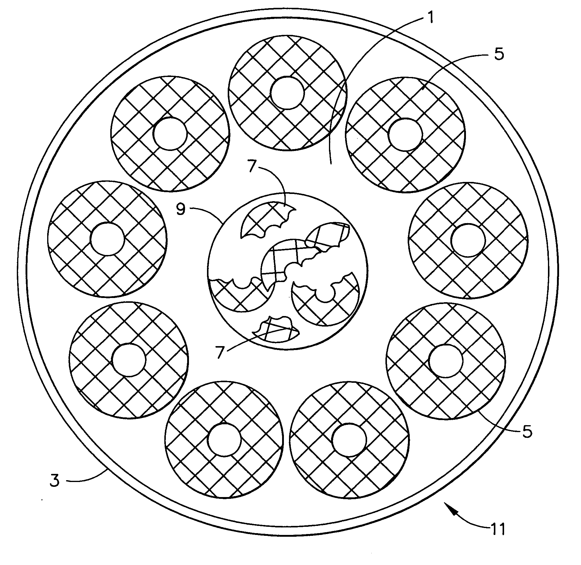
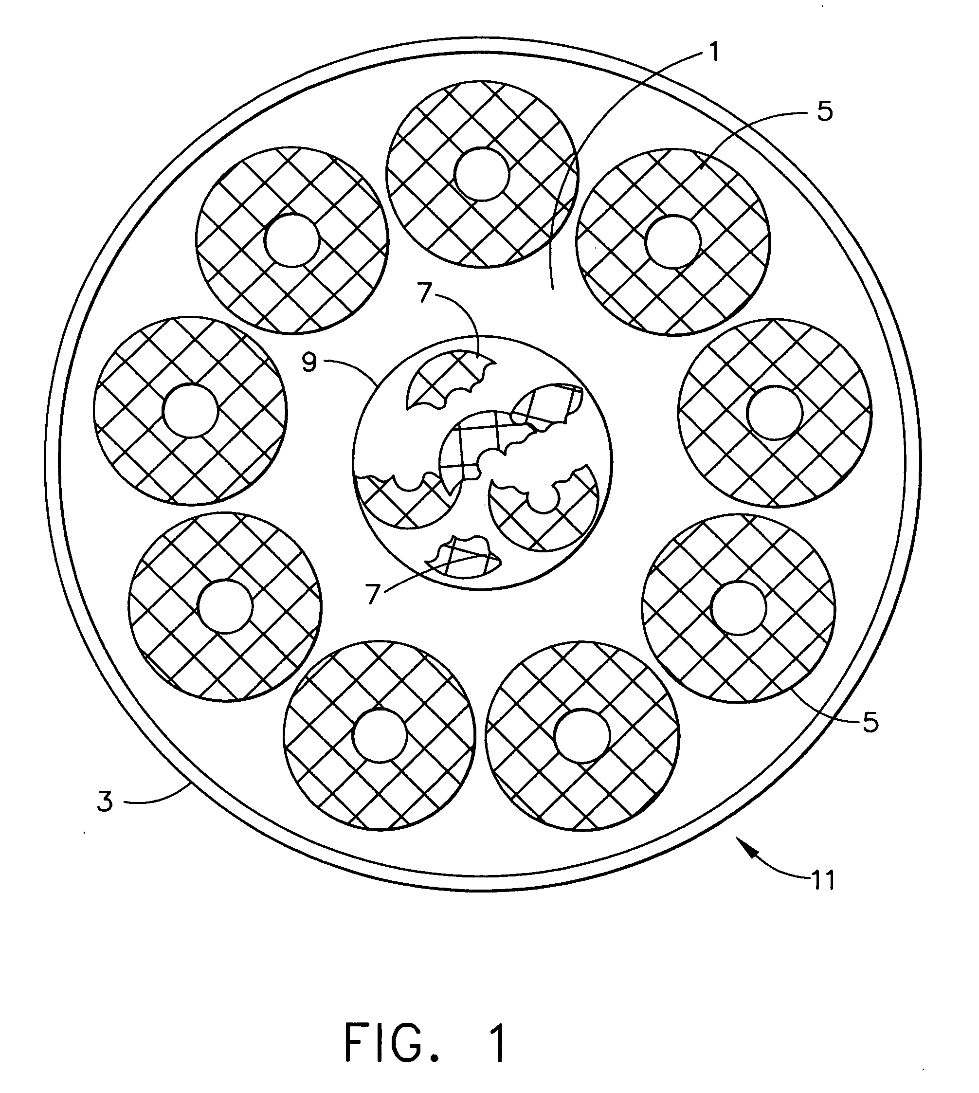
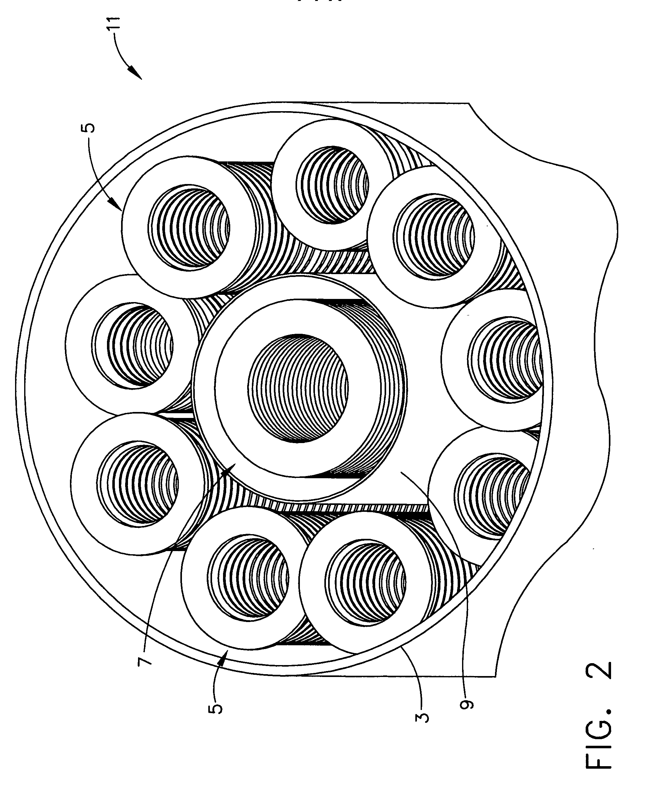
[0029] Densification. The apparatus of this invention is especially useful for carbon densification of annular porous structures used for high performance brake discs. The apparatus supports and positions a number of brake discs which are stacked on top of each other in a number of stacks. During the densification process, the apparatus and stacks of discs are enclosed in a furnace. Hot hydrocarbon gases are caused to flow around and through the stacks of brake discs, thereby depositing a carbon matrix within the interior regions and on the surface of the porous brake disc structures. The absolute gas pressure for the furnace is typically about 5-40 torr, the temperature range is typically about 950-1100° C., and the densification time is typically from 150 to 900 hours. A variety of different types of gas may be used. One may use for instance 100% natural gas. Natural gas typically comprises 92-96% methane, up to 5% ethane, up to 1% propane, up to 0.5% butane, and very small amount...


PUM

PropertyMeasurementUnit
massaaaaaaaaaa
massaaaaaaaaaa
thickaaaaaaaaaa

Abstract

Apparatus such as a furnace muffle (11) for use in a CVI / CVD furnace. The apparatus includes a bottom (12), a top (13), and an outer wall (3) defining an interior space (1) in the apparatus, and a passive heat distribution element (7, 9) located within the interior space (1) and apart from the outer wall (3). Preferably, the bottom (12) and top (12) include perforated plates and the outer wall (3) is cylindrical in shape and all are made of graphite or carbon-carbon composite material and the passive heat distribution element (7, 9) is cylindrical in shape and includes graphite or carbon-carbon composite discs having no spacers therebetween. Also, a method for densifying a porous carbon preform (5), which method includes the steps of: (a) providing the apparatus (11); (b) charging the apparatus (11) with a plurality of stacks of annular porous carbon preforms (5), the preforms being separated from one another by spacers (15); (c) locating the charged apparatus (11) in a furnace at a temperature in the range of 950-1100° C. and a pressure in the range of 5-40 torr; and (d) circulating a natural gas reactant blended with up to 15% propane through the apparatus for 150-900 hours. Also, a batch of carbon-carbon composite preforms made by the method, wherein the density of the batch of preforms is at least 0.5 g / cc higher than the density of a batch of preforms made by an otherwise identical process in which the apparatus does not contain a passive heat distribution element located within its interior. The preforms may be configured as aircraft landing system brake discs or racing car brake discs.

Description

[0001] This invention relates generally to chemical vapor infiltration and deposition (CVI / CVD) processes, and more particularly to an apparatus that can be used to carry out highly uniform CVI / CVD processes. BACKGROUND OF THE INVENTION [0002] Chemical vapor infiltration and deposition is a well known technique for depositing a binding matrix within a porous structure. The terminology “chemical vapor deposition (CVD) generally implies deposition of a surface coating, but the terminology is also used to refer to infiltration and deposition of a matrix within a porous structure. As used herein, the terminology “CVI / CVD” refers to infiltration and deposition of a matrix within a porous structure. This technique is suitable for fabricating high temperature structural composites by depositing a carbonaceous or ceramic matrix within a carbonaceous or ceramic porous structure composed of fibers, and is particularly valuable in the manufacture of useful structures such as carbon-carbon comp...

Claims


Application Information

Patent Timeline
Patent Type & Authority Applications(United States)
IPC IPC(8): B32B9/00
CPCC23C16/045Y10T428/30Y10S427/10C23C16/46
Inventor ARICO, ALAN A.PARKER, DAVID E.WAGHRAY, AKSHAYMILLER, BRIANSHAW, DAVID W.
Owner HONEYWELL INT INC
Why Eureka
Try Eureka