Sintered ceramic compact and ceramic filter

a compact and ceramic filter technology, applied in ceramicware, separation processes, machines/engines, etc., can solve the problems of large cracks in the filter itself, exhaust gas leakage, and harmful effects on the environment and the human body, so as to reduce thermal stress, effectively act on the mitigation of thermal shock, and efficiently prevent minute cracks

Inactive Publication Date: 2006-03-09
IBIDEN CO LTD
View PDF76 Cites 194 Cited by
  • Summary
  • Abstract
  • Description
  • Claims
  • Application Information

AI Technical Summary

Benefits of technology

[0034] The ceramic sintered body of the invention having the structure explained above, that is, the silicon carbide sintered body is characterized in that mean particle size ratio of the silicon carbide coarse particles to the silicon carbide fine particles is adjusted to be 15:1˜200:1 and the ratio of the total weights thereof is adjusted to be 1:1˜9:1 and that the bonding layer comprising silicon carbide fine particles and / or a polycrystalline body made of the silicon carbide fine particle group is interposed between the silicon carbide coarse particles, whereby the bonding layer can develop the function of mitigating the aforementioned thermal shock and efficiently prevent cracks from occuring in the sintered body.
[0035] Further, in the silicon carbide sintered body, by adjusting a mean particle diameter of the silicon carbide coarse particle to not less than 30 μm, the number of the bonding layers is decreased, while the number of the silicon carbide fine particles per the bonding layer is increased, so that it is possible to sufficiently ensure the thickness of the layer comprising the polycrystalline bodies constituted with the silicon carbide fine particles and / or the silicon carbide fine particle group (bonding layer) to effectively act on the mitigation of the thermal shock as described above. Moreover, the bonding layer means bonding portions wherein the silicon carbide coarse particles are connected to each other through the polycrystalline body comprising at least one silicon carbide fine particle and / or a group thereof.
[0036] In the ceramic filter according to the invention produced by using the silicon carbide sintered body, the whole of the honeycomb structural body can be enclosed and compressed by an action of the sealing material layer, and it becomes possible to efficiently prevent minute cracks generated by impact, thermal stress and the like from growing to be a visible size and silicon carbide particles from shedding accompanied with the occurrence of cracks.
[0037] In the aggregate type ceramic filter integrated by using the silicon carbide sintered bodies and combining a plurality of the honeycomb bodies prepared by these sintered bodies through the sealing material layer, there are advantages in reducing thermal stress and improving heat resistance by said sealing material layer, and adjusting the size freely by increasing and decreasing the number of the honeycomb structural bodies, whereby it becomes possible to catch particulates and the like in the exhaust gas more efficiently by the cell walls separating the cells.
[0038] Further, by utilizing the ceramic filter of the invention as the exhaust gas purifying apparatus for vehicles, it is possible to catch particulates in the exhaust gas completely for long periods, reduce the deterioration of a catalyst when it is carried, prevent the breakage of the filter since minute cracks generated by impact, thermal stress or the like do not grow to be a visible size, prevent silicon carbide particles from shedding accompanied with the occurrence of cracks, improve its heat resistance, and adjust the size freely.

Problems solved by technology

It has been pointed out that the exhaust gas discharged from internal combustion engines in vehicles such as buses or trucks, construction machines and the like contains a large number of fine particulates, and causes a harmful effect on environment and the human body.
However, when a filter made of silicon carbide is subjected to the regeneration treatment, large cracks may be generated in the filter itself due to thermal stress generated in the regeneration treatment.
The filter having the cracks has a problem that the exhaust gas leaks out from the cracks and the catching of the particulates becomes incomplete after a long-term use of the filter.
Such cracks can occur across silicon carbide particles and cause breakage of the filter.
Further, as the degree of dispersion to the honeycomb structural body becomes higher, the reaction site to the particulates and the harmful gas components increases and the activity also increases.
At a high temperature, however, the specific surface area of the catalyst carrier used for increasing the dispersion degree of the catalyst such as alumina and the like decreases and the sintering of the catalyst itself is caused.
Consequently, it is known that the dispersion degree gets worse.
Besides, in such a honeycomb structural body, the thermal conductivity is low as compared with the honeycomb structural body made only of silicon carbide, so that when the same amount of particulates is burnt at the regeneration treatment, the activity of the catalyst carried may decrease because heat from burning portions of particulates on surfaces of cells and the like is hard to disperse and the temperature of the burning portions becomes extremely high.
Therefore, in the honeycomb structural body including heat-resistant particles and metallic silicon, visible-size cracks may be generated at the regeneration treatment.

Method used


Image

  • Sintered ceramic compact and ceramic filter
  • Sintered ceramic compact and ceramic filter
  • Sintered ceramic compact and ceramic filter

Examples


example 1

of the Present Invention

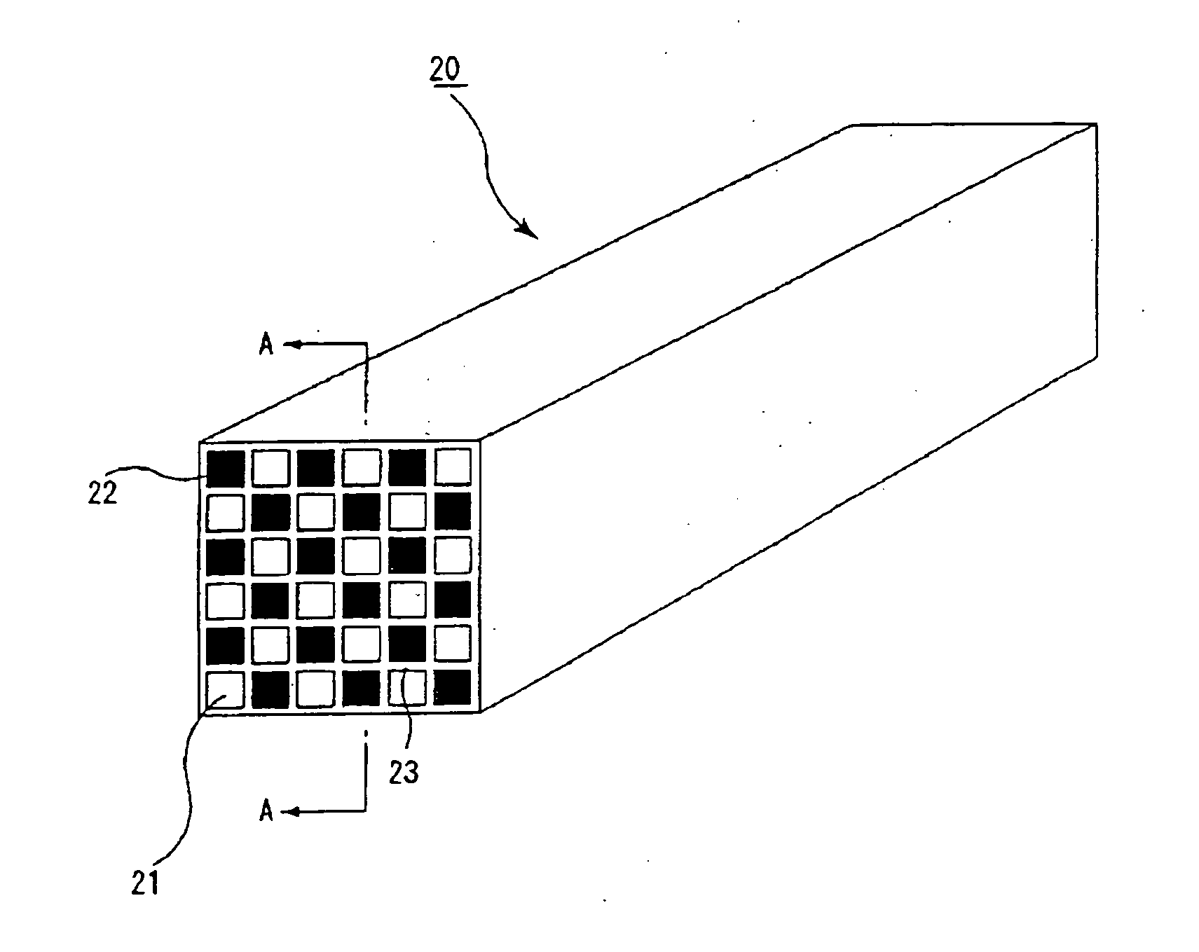
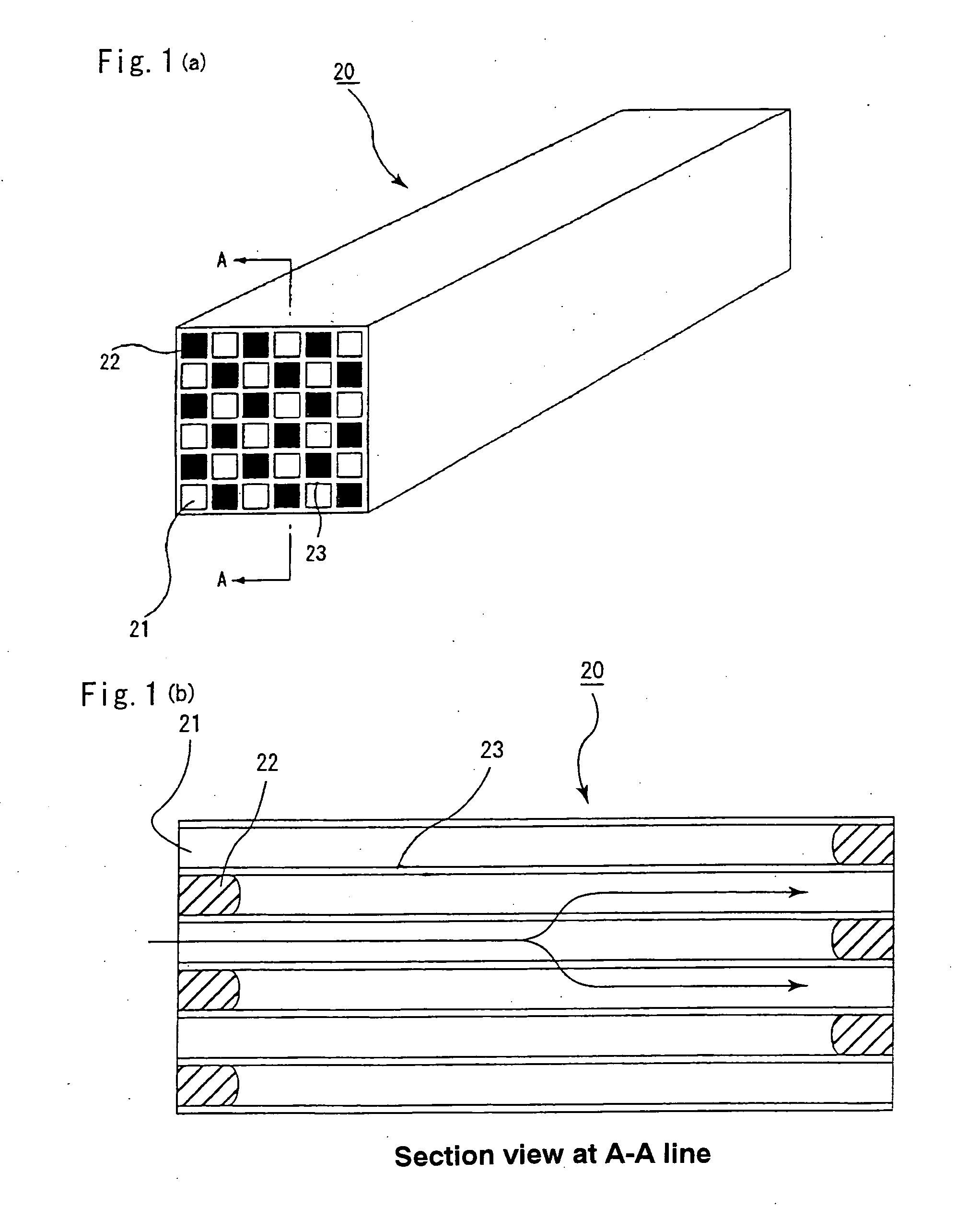
[0116] (1) A starting material paste is prepared by wet-mixing 70% by weight of α-type silicon carbide powder having an average particle size of 30 μm (silicon carbide coarse particles) with 30% by weight of α-type silicon powder having an average particle size of 0.5 μm (silicon carbide fine particles) and adding and kneading with 15 parts by weight of an organic binder (methyl cellulose) and 20 parts by weight of water based on 100 parts by weight of the resulting mixed powder. The silicon carbide fine particles are prepared by previously acid-cleaning with nitric acid, hydrofluoric acid, hydrochloric acid or the like, and then adding 0.7 parts by weight of iron powder having an average particle diameter of 0.1 μm and particle distribution within ±10% of the average particle size based on 100 parts by weight of silicon carbide fine particles.

[0117] Next, small amounts of a lubricant and a plasticizer are added to the starting material paste, mixed and knea...

reference example 1

[0125] 70% by weight of α-type silicon carbide powder having an average particle size of 30 μm (silicon carbide coarse particles) and 30% by weight of α-type silicon carbide powder having an average particle size of 0.5 μm (silicon carbide fine particles) are wet-mixed, and to 100 parts by weight of the obtained mixture are added and kneaded 15 parts by weight of an organic binder (methyl cellulose) and 20 parts by weight of water to prepare a starting material paste. The above silicon carbide fine particles are prepared by previously acid-cleaning with nitric acid, and then adding 0.7 parts by weight of iron powder having an average particle diameter of 0.1 μm and particle distribution within ±10% of the average particle diameter based on 100 parts by weight of silicon carbide fine particles.

[0126] Next, small amounts of a lubricant and a plasticizer are added to the starting material paste, further mixed and kneaded, and thereafter extrusion-molded to form a ceramic shaped body h...


PUM

PropertyMeasurementUnit
aspect ratioaaaaaaaaaa
particle sizeaaaaaaaaaa
mean particle sizeaaaaaaaaaa

Abstract

The present invention provides for a ceramic sintered body and a ceramic filter having a long-term stability which can prevent cracks from occurring due to the breakage of ceramic particles when thermal stress is applied in regeneration process and the like, and can prevent catalyst carried from deteriorating when regeneration treatment is conducted repeatedly. The invention is a ceramic sintered body comprising ceramic coarse particles and porous bonding layers existing between the ceramic coarse particles to connect the particles and comprising ceramic fine particles having an average particle size smaller than that of the ceramic coarse particles and/or the aggregates thereof, and a ceramic filter prepared by using the ceramic sintered body.

Description

RELATED APPLICATION [0001] This application is an application claiming a priority right based on Japanese Patent Application No. 2003-361229 filed on Sep. 12, 2003. TECHNICAL FIELD [0002] This invention relates to a ceramic sintered body and a ceramic filter produced by using the ceramic sintered body, and more particularly to a ceramic filter used for removing particulates discharged from an internal combustion engine such as a diesel engine or the like. Moreover, a catalyst can be carried on the ceramic filter. BACKGROUND ART [0003] It has been pointed out that the exhaust gas discharged from internal combustion engines in vehicles such as buses or trucks, construction machines and the like contains a large number of fine particulates, and causes a harmful effect on environment and the human body. Therefore, it has been required to remove and purify the particulates. In order to fulfill such requirement, a filter for purifying the exhaust gas, for example, a filter with a honeycom...

Claims


Application Information

Patent Timeline
Patent Type & Authority Applications(United States)
IPC IPC(8): C04B35/56B32B3/12B01D46/24C04B35/565C04B35/80C04B37/00C04B38/00
CPCB01D46/2418Y10T428/24157C04B35/565C04B35/626C04B35/6263C04B35/62655C04B35/6303C04B35/6316C04B35/806C04B37/005C04B38/00C04B2111/00793C04B2235/3418C04B2235/383C04B2235/402C04B2235/404C04B2235/405C04B2235/428C04B2235/5224C04B2235/5228C04B2235/526C04B2235/5427C04B2235/5436C04B2235/5472C04B2235/656C04B2235/77C04B2235/80C04B2237/083C04B2237/365F01N2450/28B32B2315/02Y10T428/24149Y10T428/249978Y10T428/249986Y10T428/249953C04B35/80
Inventor OHNO, KAZUSHIGESATO, HIROKI
Owner IBIDEN CO LTD
Why Eureka
Try Eureka