Structures and fabrication techniques for solid state electrochemical devices

a technology of electrochemical devices and structures, applied in the field of solid-state electrochemical devices, can solve the problems of inherently high electrical resistance, difficult to maintain, and high cost of ceramic materials used in conventional solid-state electrochemical device implementations, and achieve the effects of reducing resistive losses in the device, high electronic conductivity, and high strength

Inactive Publication Date: 2006-03-16
RGT UNIV OF CALIFORNIA
View PDF17 Cites 33 Cited by
  • Summary
  • Abstract
  • Description
  • Claims
  • Application Information

AI Technical Summary

Benefits of technology

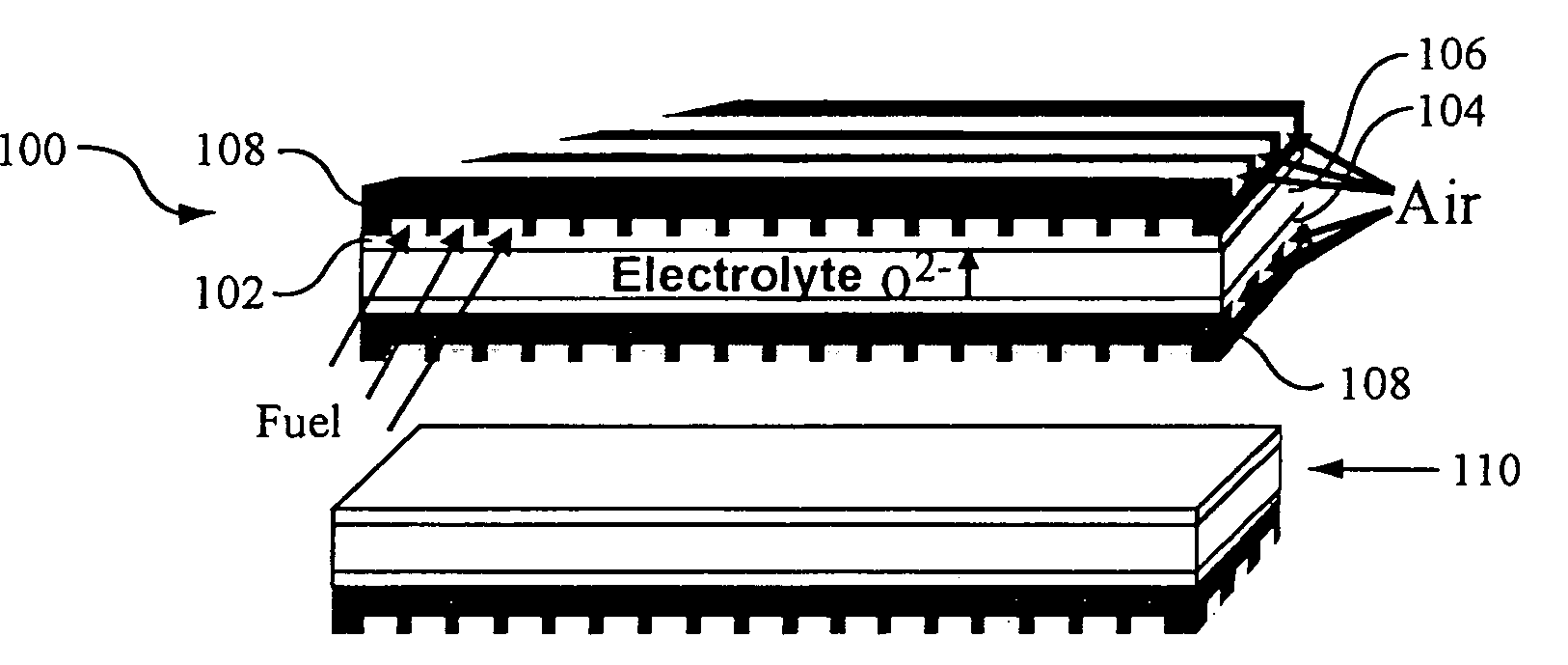
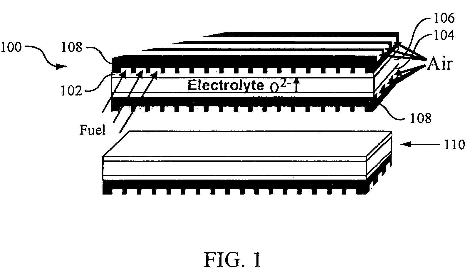
[0011] In general, the present invention provides low-cost, mechanically strong, highly electronically conductive porous structures for solid-state electrochemical devices, techniques for forming these structures, and devices incorporating the structures. In preferred embodiments, the invention provides a porous electrode designed for high strength and high electronic conductivity (to lower resistive losses in the device due to current collection). Conventional Ni—YSZ based SOFCs may be greatly improved by application of the present invention by, for example, casting a thin layer of Ni—YSZ on top of a porous high-strength alloy support—this also substantially lowers the cost of the device by using inexpensive alloy material for mechanical strength as opposed to nickel. Alternatively, alloys known to have good oxidation resistance can be used to form a high-strength air electrode in a solid state electrochemical device. In this embodiment, an alloy such as Inconel 600 is used to make a porous high-strength electrode onto which an electrolyte membrane is co-fired.

Problems solved by technology

The ceramic materials used in conventional solid state electrochemical device implementations can be expensive to manufacture, difficult to maintain (due to their brittleness) and have inherently high electrical resistance.
The resistance may be reduced by operating the devices at high temperatures, typically in excess of 900° C. However, such high temperature operation has significant drawbacks with regard to the device maintenance and the materials available for incorporation into a device, particularly in the oxidizing environment of an oxygen electrode, for example.
Resistive loss attributable to these interconnects can also be significant.
However, these Ni—YSZ supported thin-film structures are mechanically weak, and will deteriorate if exposed to air on SOFC cool-down due to the oxidation of Ni to NiO in oxidizing environments.
Also, nickel is a relatively expensive material, and to use a thick Ni—YSZ substrate as a mechanical support in a solid state electrochemical device will impose large cost penalties.
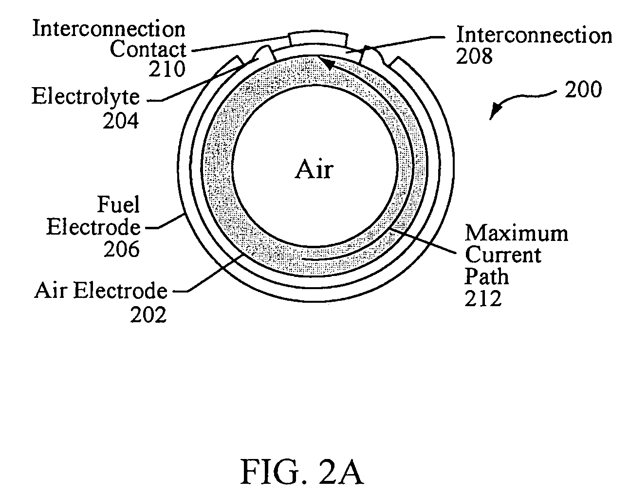
However, tubular designs provide less power density than planar designs due to their inherently relatively long current path that results in substantial resistive power loss.
Planar designs are theoretically more efficient than tubular designs, but are generally recognized as having significant safety and reliability issues due to the complexity of sealing and manifolding a planar stack.
Thus, solid state electrochemical devices incorporating current implementations of these cell designs are expensive to manufacture and may suffer from safety, reliability, and / or efficiency drawbacks.

Method used


Image

  • Structures and fabrication techniques for solid state electrochemical devices
  • Structures and fabrication techniques for solid state electrochemical devices
  • Structures and fabrication techniques for solid state electrochemical devices

Examples


example 1

Co-firing of YSZ Film on Inconel-Alumina Substrate

[0078] 50 vol % Al2O3 (AKP-30) and 50 vol % Inconel 600 (Powder Alloy Corp.) with a small amount of binder (XUS 40303 from Dow Chemical Company) were mixed in water and dried. The resulting powder was ground in a mortar and pestle and sieved to ≦100 μm. 5 g of the powder was pressed to 5000 psi in an 1.5 in steel die. A thin layer of YSZ powder (Tosoh Corp.) was applied to one surface of the pressed disk. The coated disk was again pressed to 6000 psito increase the green density of the YSZ film and enhance adhesion. The disk was placed film side down in a molybdenum furnace under 2 psi flowing He. The furnace was manually heated to 450° C., and then at a rate of 5° C. / min to 1350° C., held for 4 hr, and then cooled at a rate of 5° C. / min. The resulting bilayer shrank 10%. The film side was shiny and clear, the uncoated side was slightly pinkish (chromia scale). FIGS. 6A and 6B show a scanning electron microscope (SEM) edge view of t...


PUM

PropertyMeasurementUnit
thickaaaaaaaaaa
temperatureaaaaaaaaaa
temperaturesaaaaaaaaaa

Abstract

Low-cost, mechanically strong, highly electronically conductive porous substrates and associated structures for solid-state electrochemical devices, techniques for forming these structures, and devices incorporating the structures provide solid state electrochemical device substrates of novel composition and techniques for forming thin electrode / membrane / electrolyte coatings on the novel or more conventional substrates. In particular, in one aspect the invention provides techniques for co-firing of device substrate (often an electrode) with an electrolyte or membrane layer to form densified electrolyte / membrane films 5 to 20 microns thick. In another aspect, densified electrolyte / membrane films 5 to 20 microns thick may be formed on a pre-sintered substrate by a constrained sintering process. In some cases, the substrate may be a porous metal, alloy, or non-nickel cermet incorporating one or more of the transition metals Cr, Fe and Cu, or alloys thereof.

Description

CROSS-REFERENCE TO RELATED APPLICATIONS [0001] This application is a continuation of U.S. application Ser. No. 10 / 273,812, entitled STRUCTURES AND FABRICATION TECHNIQUES FOR SOLID STATE ELECTROCHEMICAL DEVICES filed Oct. 17, 2002; which is a divisional of U.S. application Ser. No. 09 / 626,629, entitled STRUCTURES AND FABRICATION TECHNIQUES FOR SOLID STATE ELECTROCHEMICAL DEVICES filed Jul. 27, 2000; which claims priority of U.S. Provisional Application No. 60 / 146,769, entitled ALLOY SUPPORT STRUCTURE FOR CERAMIC ELECTROCHEMICAL DEVICES, filed Jul. 31, 1999; the disclosures of which are herein incorporated by reference.BACKGROUND OF THE INVENTION [0002] This invention was made with government support in the course of or under prime contract No. DE-ACO3-76SF00098 between the U.S. Department of Energy and the University of California. The government has certain rights in this invention. [0003] The present invention relates generally to the field of solid state electrochemical devices, a...

Claims


Application Information

Patent Timeline
Patent Type & Authority Applications(United States)
IPC IPC(8): B05D3/02B01D53/32C25B9/00H01M8/12H01M8/24
CPCB01D53/326Y10T29/49115C25B9/00H01M4/8885H01M4/9025H01M4/9033H01M4/905H01M4/9066H01M8/004H01M8/1206H01M8/1213H01M8/1226H01M8/1246H01M8/1253H01M8/126H01M8/1266H01M8/2425H01M8/243H01M2008/1293H01M2300/0074Y02E60/521Y02E60/525B01D2257/108H01M8/1231Y02E60/50Y02P70/50H01M8/2432H01M8/2483
Inventor VISCO, STEVEN J.JACOBSON, CRAIG P.DEJONGHE, LUTGARD C.
Owner RGT UNIV OF CALIFORNIA
Why Eureka
Try Eureka