Fabrication method of field emitter electrode

Inactive Publication Date: 2006-03-16
SAMSUNG ELECTRO MECHANICS CO LTD
View PDF3 Cites 39 Cited by
  • Summary
  • Abstract
  • Description
  • Claims
  • Application Information

AI Technical Summary

Benefits of technology

[0020] One feature of the present invention is to fabricate the emitter electrode by applying the mixture including carbon nanotubes and a conductive polymer to the substrate, without performing a separate deposition process of carbon nanotubes as in the electrophoretic method. Thereby, the present inv

Problems solved by technology

However, it is difficult to uniformly grow carbon nanotubes on a large area substrate, and thus a process involving purifying carbon nanotubes grown by a separate process and depositing them on the substrate is generally used.
However, this method has disadvantages such as being a complicated process, and having difficulty in obtaining homogeneous dispersion of carbon nanotubes, and thereby characteristics of the field emitter electrode may be deteriorated.
Further, there is another

Method used


Image

  • Fabrication method of field emitter electrode
  • Fabrication method of field emitter electrode
  • Fabrication method of field emitter electrode

Examples


example

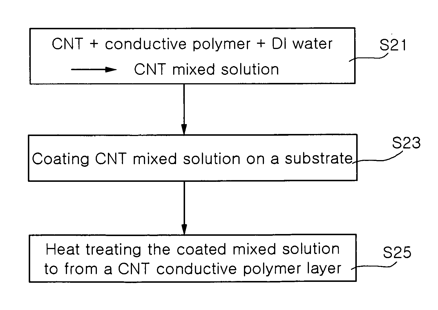
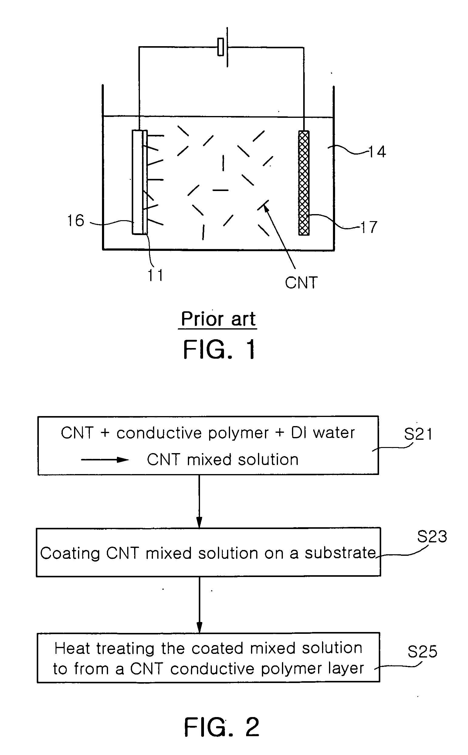
[0036] First, in order to prepare a carbon nanotube mixture in accordance with the present invention, 3 g of poly(3,4-ethylenedioxythiophene) (Baytron P, Bayer) as a conductive polymer, and 15 mg of multi-wall carbon nanotubes prepared by CVD were weighed. The conductive polymer and carbon nanotubes were mixed in 97 g of deionized water to prepare a desired carbon nanotube mixture. In order to improve substrate bond strength, 4 g of isopropenol, 1.5 g of ethylene glycol, 1.2 g of tetraethoxy silane and 1 g of acetic acid (100%), and 30 mg of benzene konium chloride (BKC) as a dispersing agent were additionally added to the carbon nanotube mixture. The carbon nanotube mixture was measured to have a viscosity of about 90 cps.

[0037] In this example, in order to accomplish homogeneous dispersion of carbon nanotubes, the carbon nanotube mixture was subjected to ultrasonic waves for 1 hour.

[0038] The carbon nanotube mixture thus obtained was applied to a copper substrate and then a spin...


PUM


Abstract

The present invention provides a process for fabricating a field emitter electrode, comprising dispersing carbon nanotubes and a conductive polymer in DI (deionized) water to prepare a carbon nanotube mixture having a viscosity of 50 to 100 cps; applying the carbon nanotube mixture to a substrate; and heat treating the carbon nanotube mixture to form a conductive polymer layer including carbon nanotubes.

Description

RELATED APPLICATION [0001] The present application is based on, and claims priority from, Korean Application No. 2004-73560, filed on Sep. 14, 2004, the disclosure of which is incorporated by reference herein in its entirety. BACKGROUND OF THE INVENTION [0002] 1. Field of the Invention [0003] The present invention relates to a process for fabricating a field emitter electrode, and more particularly to a novel process for fabricating a field emitter electrode in which low bond strength of carbon nanotubes, a disadvantage exhibited in a conventional electrophoretic method, is improved and the process is simplified. [0004] 2. Description of the Related Art [0005] Generally, a field emission device is a light source based on electron emission in vacuum and refers to an element emitting light according to the principle by which electrons emitted from micro particles are accelerated by a strong electric field to impinge upon fluorescent materials. The above-mentioned field emission device...

Claims


Application Information

Patent Timeline
IPC IPC(8): H01J9/04H01J9/14
CPCH01J9/025B82Y10/00B82Y40/00H01J1/304H01J2201/30469
Inventor KANG, HYOUNG DONGLEE, JONG MYEON
Owner SAMSUNG ELECTRO MECHANICS CO LTD
Why Eureka
Try Eureka