Transparent conductive material and transparent conductive member

Inactive Publication Date: 2006-03-23
TDK CORPARATION
View PDF3 Cites 5 Cited by
  • Summary
  • Abstract
  • Description
  • Claims
  • Application Information

AI Technical Summary

Benefits of technology

[0010] The present invention has been accomplished under the above circumstances, and an object of the invention is to provide a transparent conductive material and a transparent conductive member capable of adequately suppressing the increase and temporal change of electric resistance in the transparent conductive member even in a high humidity
[0038] When the reactive compound further has a hydrophilic group selected from the group consisting of a carboxyl group, a hydroxyl group, an amino group, and an amine derivative group, in the molecule, dispersion of the conductive powder is improved in the transparent conductive material containing the reactive compound having the hydrophilic group. In this case, a transparent conductive member with lower haze value can be obtained from this transparent conductive material, when compared with the transparent conductive materials wherein the conductive powder aggregates. In the transparent conductive material, the conductive powder is uniformly dispersed and the contact area described later is increased between the crosslinked polymer and the conductive powder, whereby it becomes feasible to obtain a transparent conductive member more improved in total strength.

Problems solved by technology

Therefore, the resins in the above documents failed to completely solve the aforementioned problem, and the Inventors presumed that the increase and temporal change of electric resistance in the transparent conductive member could be caused by disconnection of junctions between particles of the conductive powder.

Method used


Image

  • Transparent conductive material and transparent conductive member
  • Transparent conductive material and transparent conductive member

Examples


first embodiment

of Transparent Conductive Member

[0042] First, the first embodiment of the transparent conductive member of the present invention will be described.

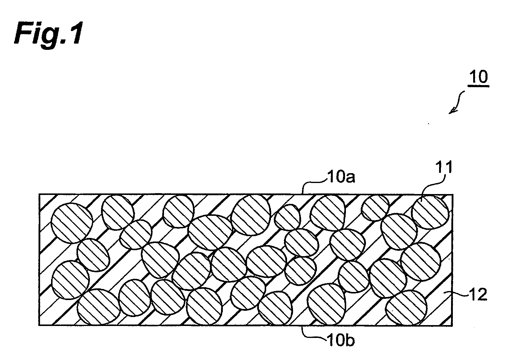
[0043]FIG. 1 is a schematic sectional view showing the first embodiment of the transparent conductive member of the present invention. As shown in FIG. 1, the transparent conductive member 10 of the present embodiment has conductive powder 11 and crosslinked polymer 12. The conductive powder 11 is filled in the transparent conductive member 10 and the conductive powder 11 is fixed to the crosslinked polymer 12.

[0044] In the transparent conductive member 10, particles of conductive powder 11 are preferably in contact with each other and the conductive powder 11 is exposed in part in surface 10a or 10b of transparent conductive member 10. For this reason, the transparent conductive member 10 can have sufficient electric conductivity.

[0045] The transparent conductive member 10 can adequately suppress the increase and temporal change of el...

second embodiment

of Transparent Conductive Member

[0091] Next, the second embodiment of the transparent conductive member of the present invention will be described. Identical or equivalent components to those in the first embodiment will be denoted by the same reference symbols, without redundant description.

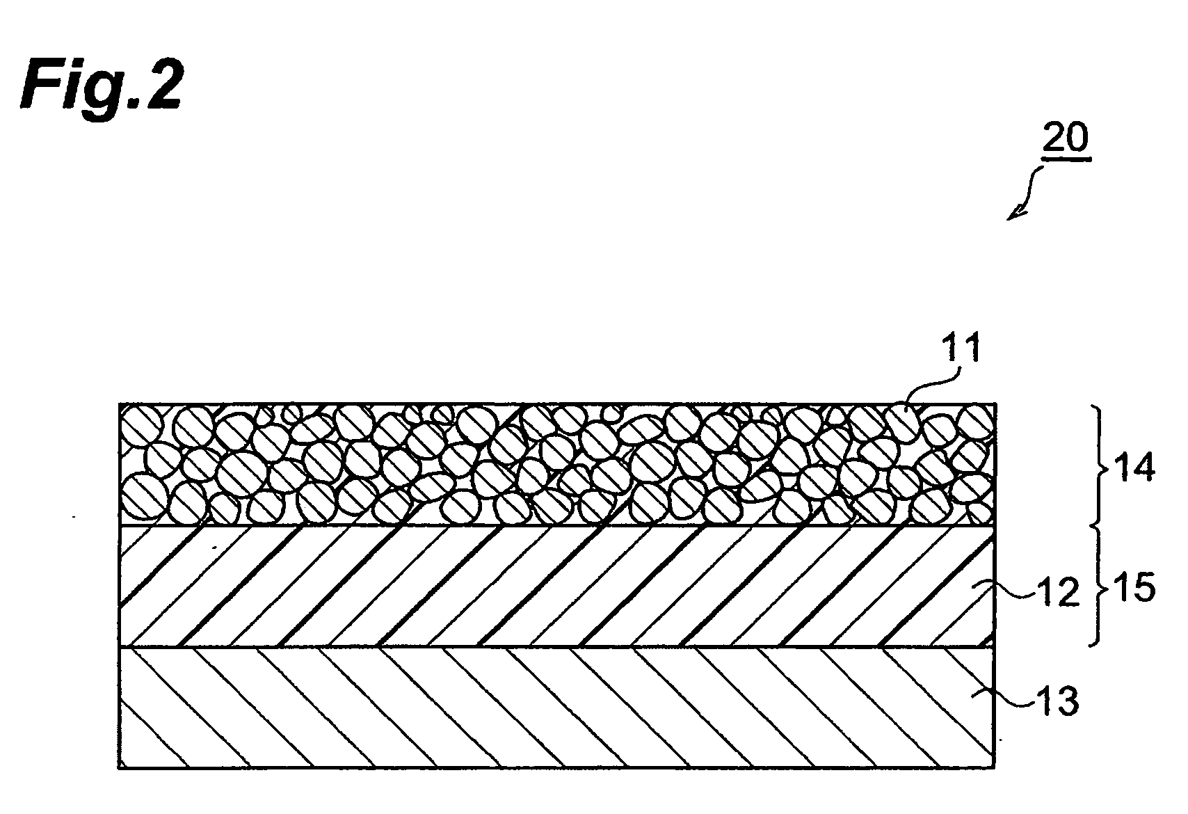
[0092]FIG. 2 is a schematic sectional view showing the second embodiment of the transparent conductive member of the present invention. As shown in FIG. 2, the transparent conductive member 20 of the present embodiment is comprised of a transparent conductive layer 14 containing a conductive powder 11, a crosslinked polymer layer 15 comprised of a crosslinked polymer 12, and a support 13, and the crosslinked polymer layer 15 and transparent conductive layer 14 are successively layered on the support 13. The transparent conductive layer 14 is filled with the conductive powder 11, and the crosslinked polymer 12 having penetrated exists between particles of conductive powder 11. The crosslinked po...

example 1

[0113] A transparent conductive material of paste form was prepared by mixing 17.75 g of the above ITO powder (conductive powder), 3 g of phenoxy polyethylene glycol acrylate (additive, available from Shin-Nakamura Chemical Co., Ltd), 6 g of an acrylic polymer (reactive compound having the average molecular weight of about 50,000, and containing 50 vinyl groups (reactive functional groups) on average and 25 groups of triethoxy silane (organic groups) on average), 3 g of A-TMMT (multifunctional organic compound, available from Shin-Nakamura Chemical Co., Ltd.), 30 g of acetone (available from Kanto Chemical Co., Inc.), and 0.24 g of a UV polymerization initiator (Ciba Specialty Chemicals) and dispersing them with a homogenizer. This transparent conductive material was applied onto a 50 mm-square glass substrate by spin coating, acetone was then removed, and the material was exposed to UV light (at the intensity of 160 W / cm) emitted from a high-pressure mercury lamp in a nitrogen atmo...


PUM


Abstract

The present invention provides a transparent conductive material containing a conductive powder, a reactive compound having an organic group capable of being bound to the conductive powder, and reactive functional groups; and a multifunctional organic compound capable of being bound to the reactive compound.

Description

BACKGROUND OF THE INVENTION [0001] 1. Field of the Invention [0002] The present invention relates to a transparent conductive material and a transparent conductive member. [0003] 2. Related Background Ad [0004] Transparent electrodes are used in LCDs, PDPs, organic EL displays, touch panels, etc. and transparent conductive members are used as the transparent electrodes. The transparent conductive members are made of transparent conductive oxide materials, and it is conventionally known that such transparent conductive oxide materials include metal oxides such as tin oxide, indium-tin complex oxide, indium oxide, zinc oxide, and zinc-antimony complex oxide. [0005] These transparent conductive member are normally made in a film form by sputtering and, however, they have some problems: e.g., equipment is expensive; efficiency of film formation is low; the film is easy to crack, and so on. On the other hand, there are also studies on the transparent conductive members based on complex s...

Claims


Application Information

Patent Timeline
IPC IPC(8): H01B1/04H01B1/00
CPCH01B1/20H01B1/08C08L2201/10B32B2307/202
Inventor YASUDA, NORIYUKI
Owner TDK CORPARATION
Why Eureka
Try Eureka