Design and synthesis of guest-host nanostructures to enhance ionic conductivity across nanocomposite membranes

a nanocomposite membrane and nanostructure technology, applied in the field of ion conducting membranes, can solve the problems of high system cost, limited wide-spread commercialization of solid oxide fuel cells, and limited ionic conductivity enhancement of guest-host nanostructures, and achieve high conductivity and ionic conductivity. high

Inactive Publication Date: 2006-03-23
THE UNITED STATES AS REPRESENTED BY THE DEPARTMENT OF ENERGY
View PDF21 Cites 29 Cited by
  • Summary
  • Abstract
  • Description
  • Claims
  • Application Information

AI Technical Summary

Benefits of technology

[0013] It is one advantage of the present invention to provide an ion conducting nanocomposite membrane with at least an order-of-magnitude higher ionic conductivity than the best currently available ceramic membranes.
[0014] It is another advantage of the present invention to provide a nanostructured membrane useful in sensor arrays, catalysis, magnetic memory arrays, quantum-dot arrays, photonic crystals, microfabricated fluidic devices, microelectro-mechanical systems, solar cells, sele

Problems solved by technology

A major technological challenge is regarding how to create and utilize these potential “candidate” conducting oxides in the form of thin-layer membranes (see, De Jonghe et al., “Supported electrolyte thin film synthesis of solid oxide fuel cells,”Annu. Rev. Mater. Res., 33, 169, 2003; and Will et al., “Fabrication of thin electrolytes for second-generation solid oxide fuel cells,”Solid State Ionics, 131, 79, 2000) that promise much higher ionic conductivity across the membrane than any existing c

Method used


Image

  • Design and synthesis of guest-host nanostructures to enhance ionic conductivity across nanocomposite membranes
  • Design and synthesis of guest-host nanostructures to enhance ionic conductivity across nanocomposite membranes
  • Design and synthesis of guest-host nanostructures to enhance ionic conductivity across nanocomposite membranes

Examples


Embodiment Construction

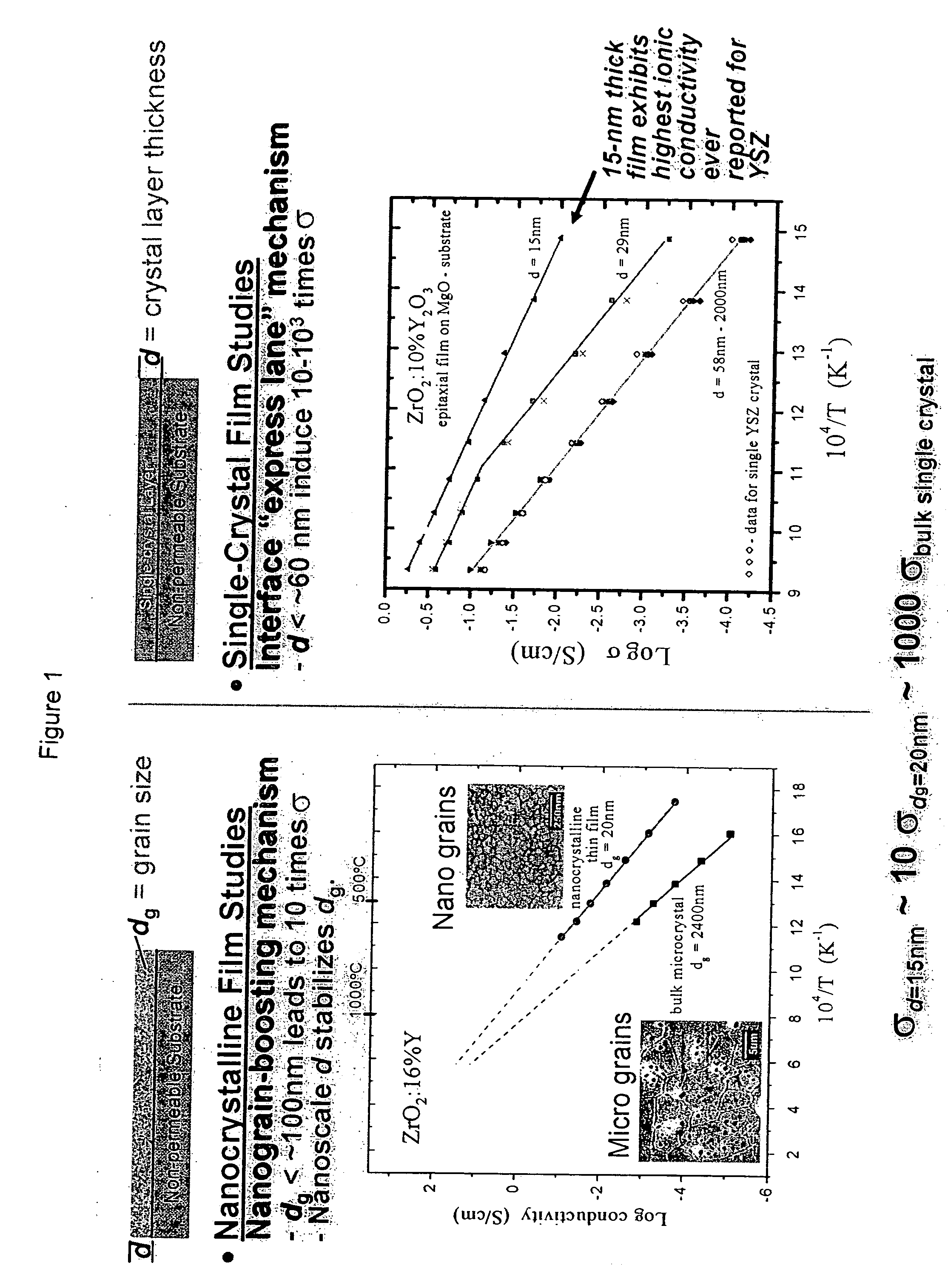
[0022] As mentioned above, ionic conductivity in solid electrolytes can be improved by dissolving appropriate impurities / dopants into the structure or by introducing interfaces (such as grain boundaries) that cause the redistribution of ions in the space-charge regions. However, doping has its limitations in enhancing conductivity. It has been discovered that for ionic conducting oxides, it is important to apply grain-boundary engineering and tailored control of nanostructures as strategies to enhance their ionic conductivity across / through a membrane.

[0023] Studies of the electrical properties of single-layer yttrium-stabilized zirconia (YSZ) thin films deposited on a magnesium oxide substrate are shown in FIG. 1 which demonstrates that it is possible to greatly enhance conductivity by nanoscale control. Nanocrystalline film studies show a nanograin conductivity boosting mechanism. When the grain size (dg) g). This may be called a “grain boundary effect” conductivity enhancement m...


PUM


Abstract

An ion conducting membrane has a matrix including an ordered array of hollow channels and a nanocrystalline electrolyte contained within at least some or all of the channels. The channels have opposed open ends, and a channel width of 1000 nanometers or less, preferably 60 nanometers or less, and most preferably 10 nanometers or less. The channels may be aligned perpendicular to the matrix surface, and the length of the channels may be 10 nanometers to 1000 micrometers. The electrolyte has grain sizes of 100 nanometers or less, and preferably grain sizes of 1 to 50 nanometers. The electrolyte may include grains with a part of the grain boundaries aligned with inner walls of the channels to form a straight oriented grain-wall interface or the electrolyte may be a single crystal. In one form, the electrolyte conducts oxygen ions, the matrix is silica, and the electrolyte is yttrium doped zirconia.

Description

STATEMENT REGARDING FEDERALLY SPONSORED RESEARCH [0001] This invention was made with Government support under Contract No. DE-AC05-00OR22725 awarded to UT-Battelle, LLC, by the U.S. Department of Energy. The Government has certain rights in this invention.CROSS-REFERENCES TO RELATED APPLICATIONS [0002] Not Applicable. BACKGROUND OF THE INVENTION [0003] 1. Field of the Invention [0004] This invention relates an ion conducting membrane having a matrix including an ordered array of hollow channels and a nanocrystalline electrolyte contained within at least some of the channels. The channels have opposed open ends, and a channel width of 1000 nanometers or less, and most preferably, the channels have a width of 10 nanometers or less. The electrolyte has grain sizes of 100 nanometers or less, and preferably the electrolyte has grain sizes of 1 to 50 nanometers. In one form, the electrolyte conducts oxygen ions, the matrix is silica, and the electrolyte is yttrium doped zirconia. [0005] 2...

Claims


Application Information

Patent Timeline
IPC IPC(8): H01M8/10G01N27/26
CPCB82Y10/00B82Y30/00Y02E60/525H01M2008/1293Y02E60/521H01M8/1246Y02E60/50Y02P70/50
Inventor HU, MICHAEL Z.KOSACKI, IGOR
Owner THE UNITED STATES AS REPRESENTED BY THE DEPARTMENT OF ENERGY
Why Eureka
Try Eureka