Means of removing particles from a membrane mask in a vacuum

a vacuum and membrane mask technology, applied in the field of electro-beam projection lithography system, can solve the problems of substantially more laser power and probably much slower speed

Inactive Publication Date: 2006-04-13
NIKON CORP
View PDF13 Cites 11 Cited by
  • Summary
  • Abstract
  • Description
  • Claims
  • Application Information

AI Technical Summary

Benefits of technology

[0013] It is therefore an aim of the present invention to provide a method for cleaning a

Problems solved by technology

The latter requires substantially more

Method used


Image

  • Means of removing particles from a membrane mask in a vacuum
  • Means of removing particles from a membrane mask in a vacuum
  • Means of removing particles from a membrane mask in a vacuum

Examples


Embodiment Construction

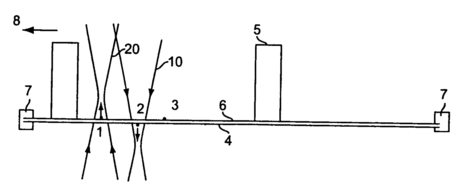
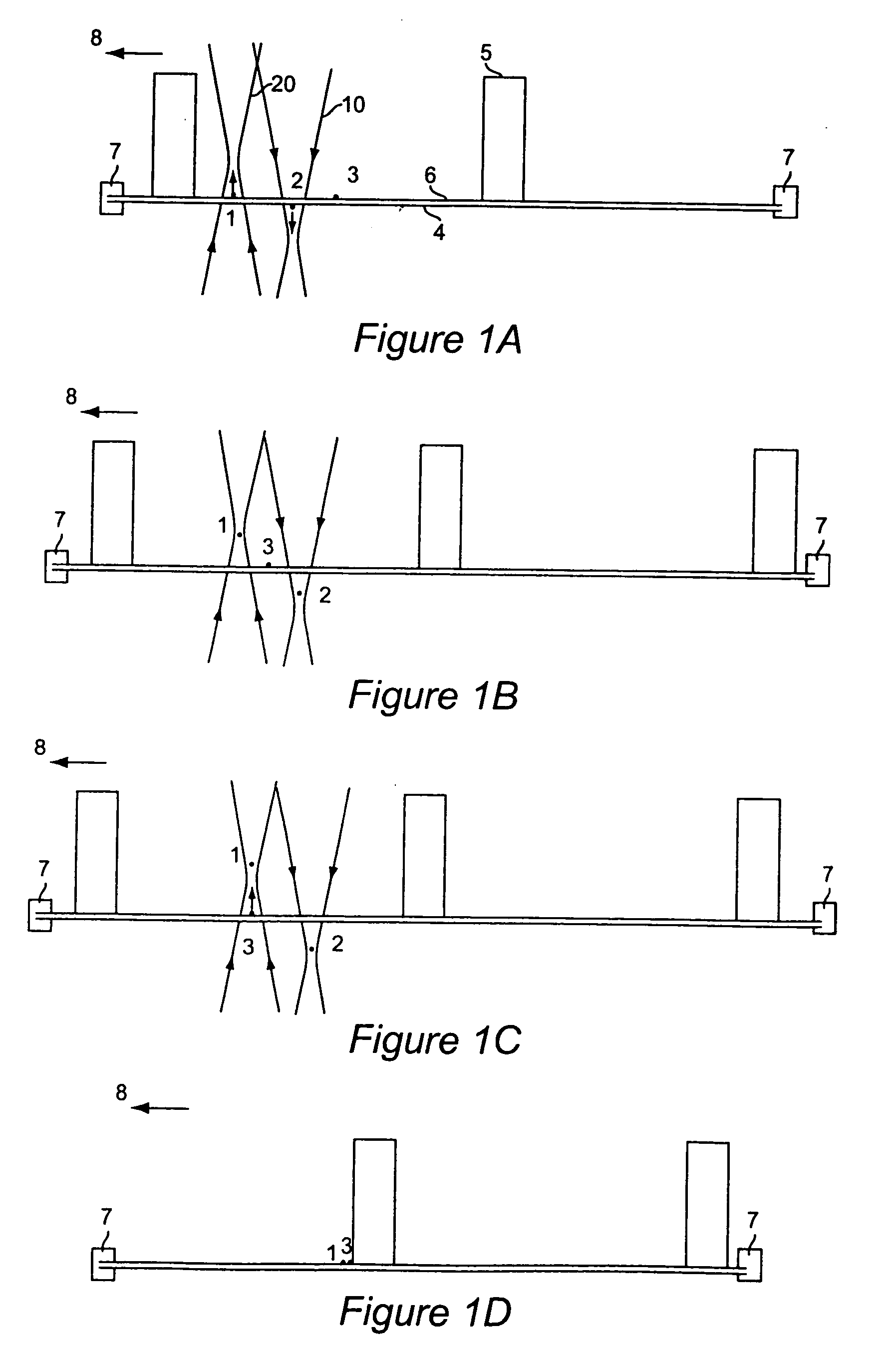
[0031] The most effective way to clean particles from a reticle is to apply optical levitation forces to remove the particles. Specifically, a combination of radiation pressure and laser gradient forces seems best suited for this application. In order to be effective, the laser forces must be greater than the reticle-particle adhesive forces. However, taking account of the wide nature and physics of adhesive forces, it is difficult to determine a “typical” adhesive force.

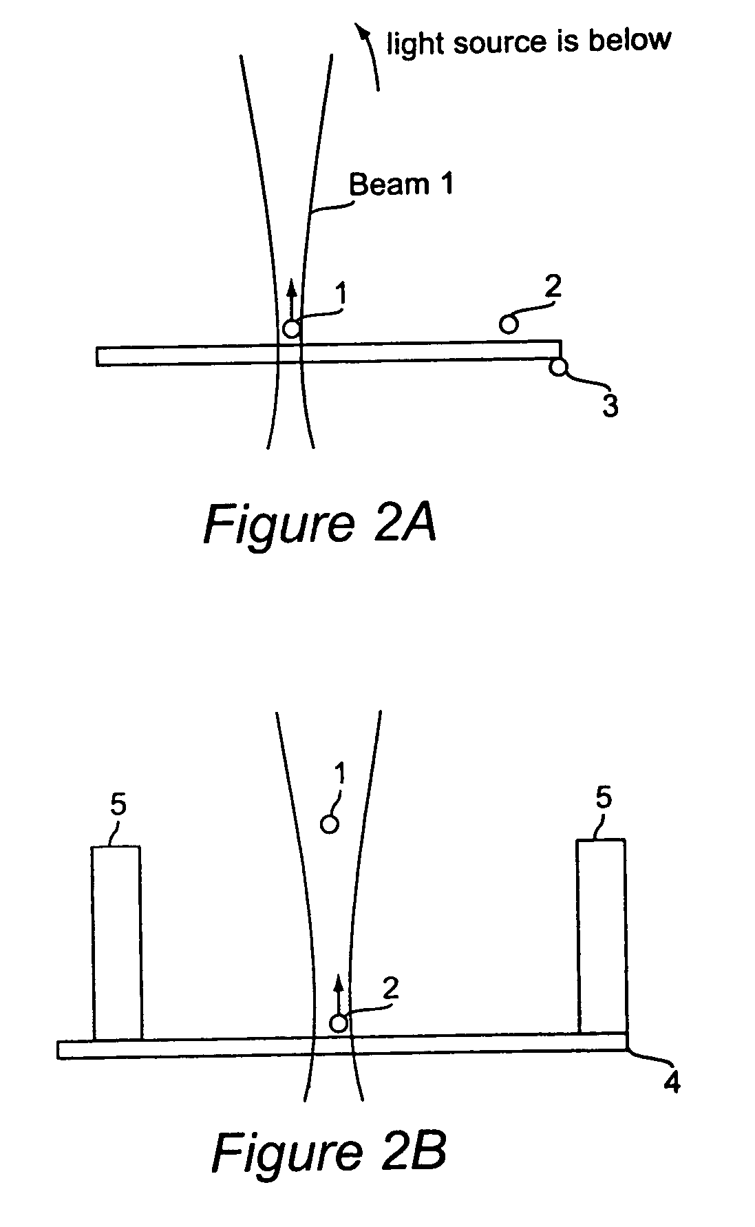
[0032] By focusing a single laser beam with a high numerical aperture (NA) objective lens, a gradient field of light intensity is created with high intensity values in the focal volume and lower in the periphery. If the interaction with a particle is primarily determined by beam refraction and when the absorption is negligible, the net force acts toward the focal volume. The net force (trapping force) can be used to “pull” and to confine micro- and nanometer-sized objects in the focal volume. Additionally, a radiat...


PUM


Abstract

A method of removing particles from a membrane reticle by a laser beam or beams. The particles on the bottom of the reticle are knocked off and fall away and particles on the top are removed a short distance from the surface and deposited on or near the strut wall and then released. Alternatively, the particles are dragged or rolled to the vicinity of the strut wall.

Description

BACKGROUND OF THE INVENTION [0001] 1. Field of the Invention [0002] The present invention generally relates to an Electron Beam Projection Lithography System (EPL) and, more particularly, to cleaning a membrane reticle in an Electron Beam Projection System from contamination particles by using a laser beam. [0003] 2. Background Description [0004] Lithography is an important method used in the electronic industry for fabricating circuit chips. Recently, electron beam projection lithography (EPL) exposure systems have been developed which are expected to offer high resolution and enhanced throughput. This system directs a relatively large area electron beam onto a portion (“subfield”) of a reticle containing the pattern associated with a specific process step for a semiconductor device. The electron beam transmitted through the reticle is projected onto a wafer where it forms a demagnified image of the illuminated part of the reticle. The reticle and wafer are mounted on precision hig...

Claims


Application Information

Patent Timeline
IPC IPC(8): G03B27/52
CPCG03F7/70866G03F7/70925
Inventor SOGARD, MICHAEL
Owner NIKON CORP
Why Eureka
Try Eureka