LPP type extreme ultra violet light source apparatus and driver laser for the same

a technology of extreme ultra violet light source and driver laser, which is applied in the direction of photomechanical equipment, instruments, and active medium materials, can solve the problems of limited operation at about 2 khz, damage to optical elements through which the laser beam is transmitted, and large damage to optical elements, so as to increase the amplifier's amplification efficiency

Active Publication Date: 2006-04-13
GIGAPHOTON
View PDF13 Cites 25 Cited by
  • Summary
  • Abstract
  • Description
  • Claims
  • Application Information

AI Technical Summary

Benefits of technology

[0025] According to the present invention, by suppressing amplitude of the oscillation spectrum that exhibits an energy peak value of the laser beam, the oscillation of other spectrums is promoted and the laser beam is short-pulsed, and therefore, short-pulsed and multi-spectrum oscillation can be performed. As a result, the amplification efficiency in the amplifier can be increased and the short-pulsed laser beam can be amplified to a higher level.

Problems solved by technology

Here, if Ep is larger, the damage on optical elements through which the laser beam is transmitted becomes also larger, and thereby, the optical elements deteriorate rapidly.
The reason is that, although there is a TEA (Transverse Excitation Atmospheric) CO2 laser as another pulsed CO2 laser, the operation at about 2 kHz is a limit in the current technology.
As in conventional technologies, in the RF-CO2 short-pulse laser using Q-switching, since the laser gas pressure is low (generally, 40 Torr to 100 Torr), broadening of each CO2 laser transition is not sufficient and the gain spectrum is modulated in a comb-like pattern.
That is, since only one spectrum contributes to amplification and the rest of the spectrums cannot be laser-oscillated and contribute to amplification, and thereby, a great part of gain is wasted.
This means that high output is not obtained in the amplification in the amplification stage.

Method used


Image

  • LPP type extreme ultra violet light source apparatus and driver laser for the same
  • LPP type extreme ultra violet light source apparatus and driver laser for the same
  • LPP type extreme ultra violet light source apparatus and driver laser for the same

Examples


first embodiment

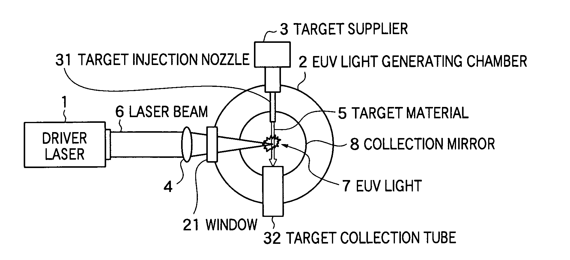
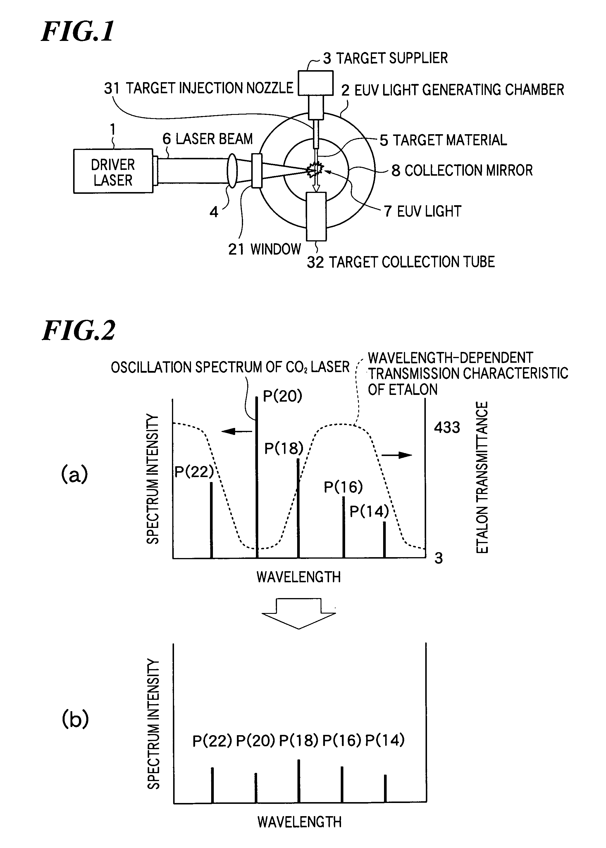
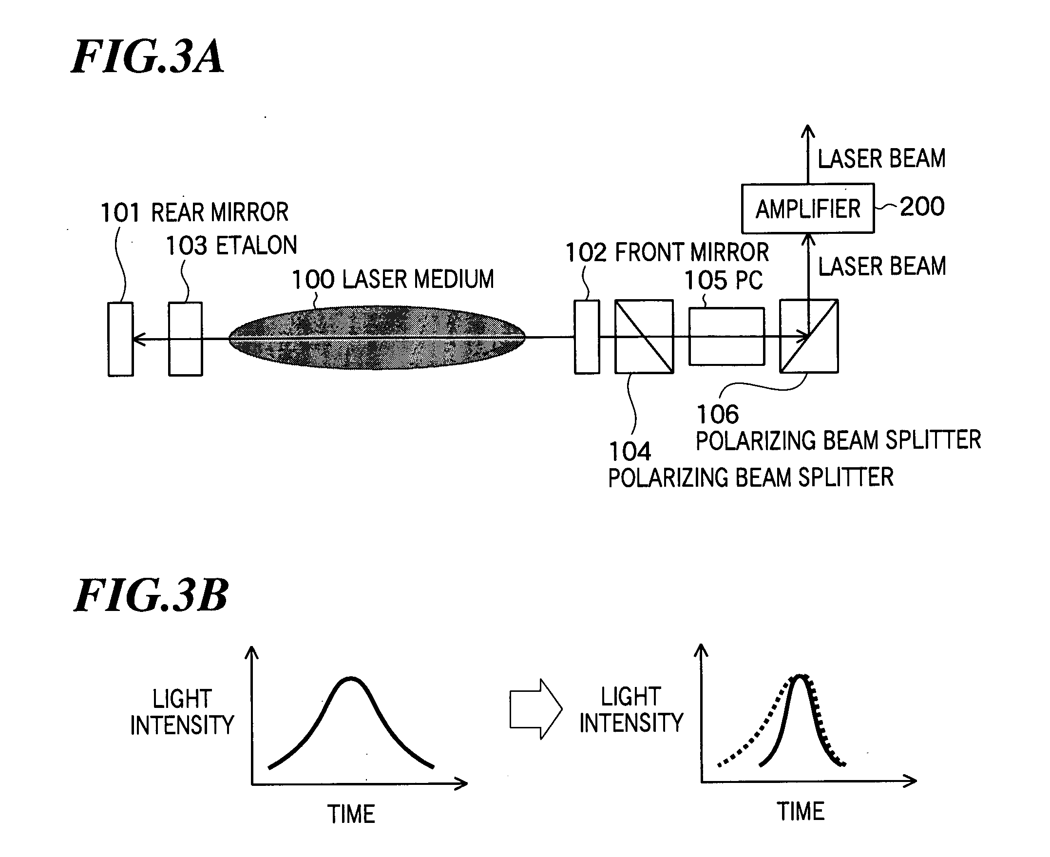
[0044] Next, a driver laser according to the present invention will be described. The embodiment is characterized by using a short-pulse multi-spectrum (multi-line) CO2 laser as an oscillation stage laser in the driver laser 1 (oscillation amplification type laser device). Since the use of the short-pulse multi-spectrum CO2 laser enables utilization of amplification ability in the amplification stage with high efficiency, high-power short pulses can be obtained by the amplification stage. The oscillation amplification type laser with such a short-pulse multi-spectrum CO2 laser as the oscillation amplification is used as a laser beam application source in the LPP type EUV light source apparatus for generating EUV light by applying a laser beam to a target material of xenon (Xe), tin (Sn), or the like. Thereby, a high-energy short-pulsed laser beam is applied to a target material and conversion efficiency from the applied laser beam into EUV light becomes higher, and it is useful to a...

second embodiment

[0070] Next, a driver laser according to the present invention will be described by referring to FIGS. 8 and 9.

[0071]FIG. 8 is a schematic diagram showing a constitution of the driver laser according to the embodiment. The driver laser includes a solid-state laser 160, a nonlinear crystal A: 161, a nonlinear crystal B: 162, and an amplifier 300. The embodiment is characterized by using the solid-state laser 160 for oscillating short pulses as the oscillation stage laser in the driver laser shown in FIG. 1. Further, a CO2 laser is used as the amplification stage laser (amplifier 300).

[0072] As shown in FIG. 8, in the embodiment, in order to realize multi-transverse mode oscillation in the wavelength region around 10 μm, two kinds of nonlinear crystals (nonlinear crystal “A”: 161 and nonlinear crystal “B”: 162) as optical parametric oscillation devices are used with the solid-state laser 160. Further, desirably, a spectrum matching box 163 is used in the subsequent stage of the optic...


PUM


Abstract

A driver laser for EUV light source apparatus which driver laser simultaneously achieves short-pulsing and multi-line oscillation. The driver laser includes: a short-pulse multi-line oscillated CO2 laser oscillator having a device that shortens width of pulses included in a laser beam to be output and a device that suppresses amplitude of an oscillation spectrum exhibiting an energy peak value; and at least one amplifier that inputs the laser beam output from the short-pulse multi-line oscillated CO2 laser oscillator and amplifies the input laser beam to output the amplified laser beam.

Description

BACKGROUND OF THE INVENTION [0001] 1. Field of the Invention [0002] The present invention relates to an LPP (laser produced plasma) type EUV (extreme ultra violet) light source apparatus for generating extreme ultra violet light to be used for exposure of semiconductor wafers or the like. Further, the present invention relates to a driver laser for applying light to a target in the LPP type EUV light source apparatus. [0003] 2. Description of a Related Art [0004] Recently, as semiconductor processes become finer, the photolithography has been making rapid progress to finer fabrication, and, in the next generation, microfabrication of 100 nm to 70 nm, further, microfabrication of 50 nm or less will be required. For example, in order to fulfill the requirement for microfabrication of 50 nm or less, the development of exposure equipment with a combination of an EUV light source for generating ultra violet light of about 13 nm in wavelength and a reduced projection catoptric system is e...

Claims


Application Information

Patent Timeline
Patent Type & Authority Applications(United States)
IPC IPC(8): H01S3/00
CPCB82Y10/00G03F7/70033H01S3/0057H01S3/08004H01S3/08009H01S3/1075H01S3/108H01S3/1083H01S3/1103H01S3/2232H01S3/23H01S3/2308H01S3/235
Inventor ENDO, AKIRAARIGA, TATSUYASUGANUMA, TAKASHIMIURA, TAISUKE
Owner GIGAPHOTON
Why Eureka
Try Eureka