
Polarizing plate and liquid crystal display employing the same

a technology of liquid crystal display and polarizing plate, which is applied in the direction of polarizing elements, instruments, transportation and packaging, etc., can solve the problems of reducing the productivity or manufacturing cost of the product, the viewing angle is small, and the thickness cannot be increased, so as to reduce the dimensional change (shape change), the effect of excellent optical properties and simple constitution

Inactive Publication Date: 2006-04-20
KONICA CORP
View PDF3 Cites 14 Cited by
  • Summary
  • Abstract
  • Description
  • Claims
  • Application Information

AI Technical Summary

Benefits of technology

[0181] In the invention, it is essential that the cellulose ester film in the invention be provided on at least one side of the polarizing film of the polarizing plate. Although cellulose triacetate (TAC) film used in the support of a conventional polarizing plate may be provided on the other side of the polarizing film of the polarizing plate, all the cellulose ester films used in the polarizing plate are preferably the cellulose ester film in the invention in view of similarity in physical properties of both surfaces of the polarizing plate, whereby the effect of the invention is obtained most efficiently.
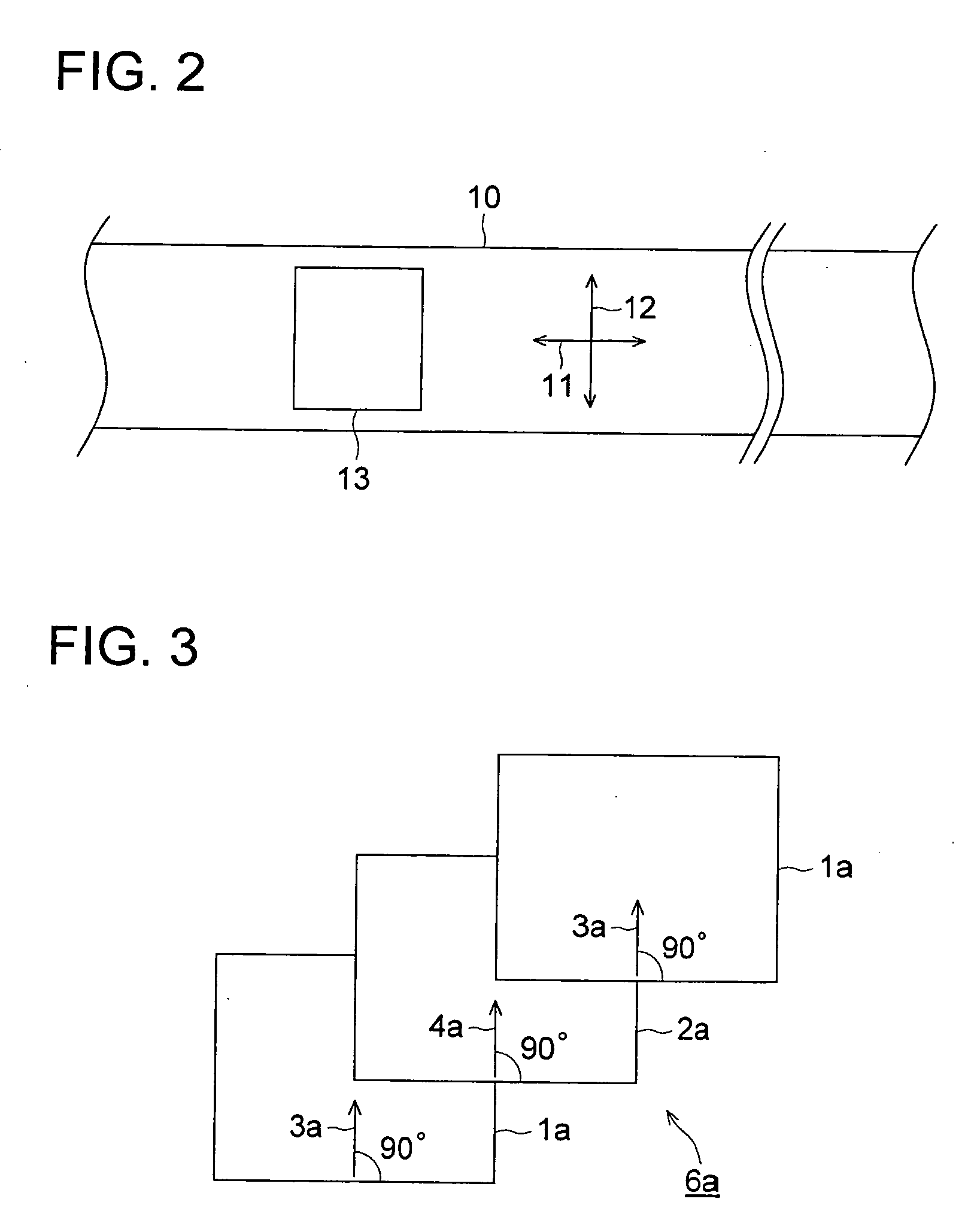
[0182] A polarizing plate, which comprises the cellulose ester film in the invention, and provided thereon, a polarizing film and a second cellulose acetate film having been stretched in the transverse direction in that order, provides a polarizing plate with phase difference function which provides reduced dimensional change (shape change) under various temperature and humidity circumstances, and maintains excellent optical properties. The stretching in the transverse direction may be carried out during or after the film manufacture, however, it is preferred in view of productivity or uniformity of stretching that the stretching is continuously carried out during the film manufacture. The stretching magnification is preferably from 1.01 to 1.2, more preferably from 1.03 to 1.15, and most preferably from 1.05 to 1.10. The second cellulose acetate film is preferably cellulose triacetate (TAC) film.
[0183] In the above polarizing plate, the ratio A / B of stretching magnification A of the cellulose ester film in the invention provided on one side of the polarizing film to stretching magnification B of the cellulose triacetate film provided on the other side of the polarizing film is preferably from 1000 to 0.001, more preferably from 200 to 0.005, and still more preferably from 100 to 0.01.
[0184] The polarizing plate is preferably a polarizing plate in which the casting direction during manufacture of the cellulose ester film in the invention is approximately parallel with the stretching direction of the polarizing film. The thus obtained polarizing plate is provided on both sides of a liquid crystal cell, and preferably has the following constitution.
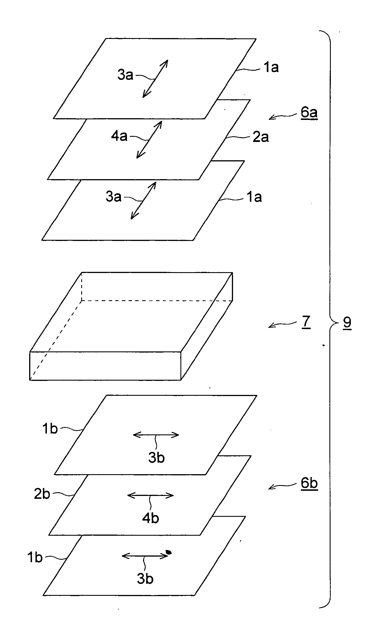
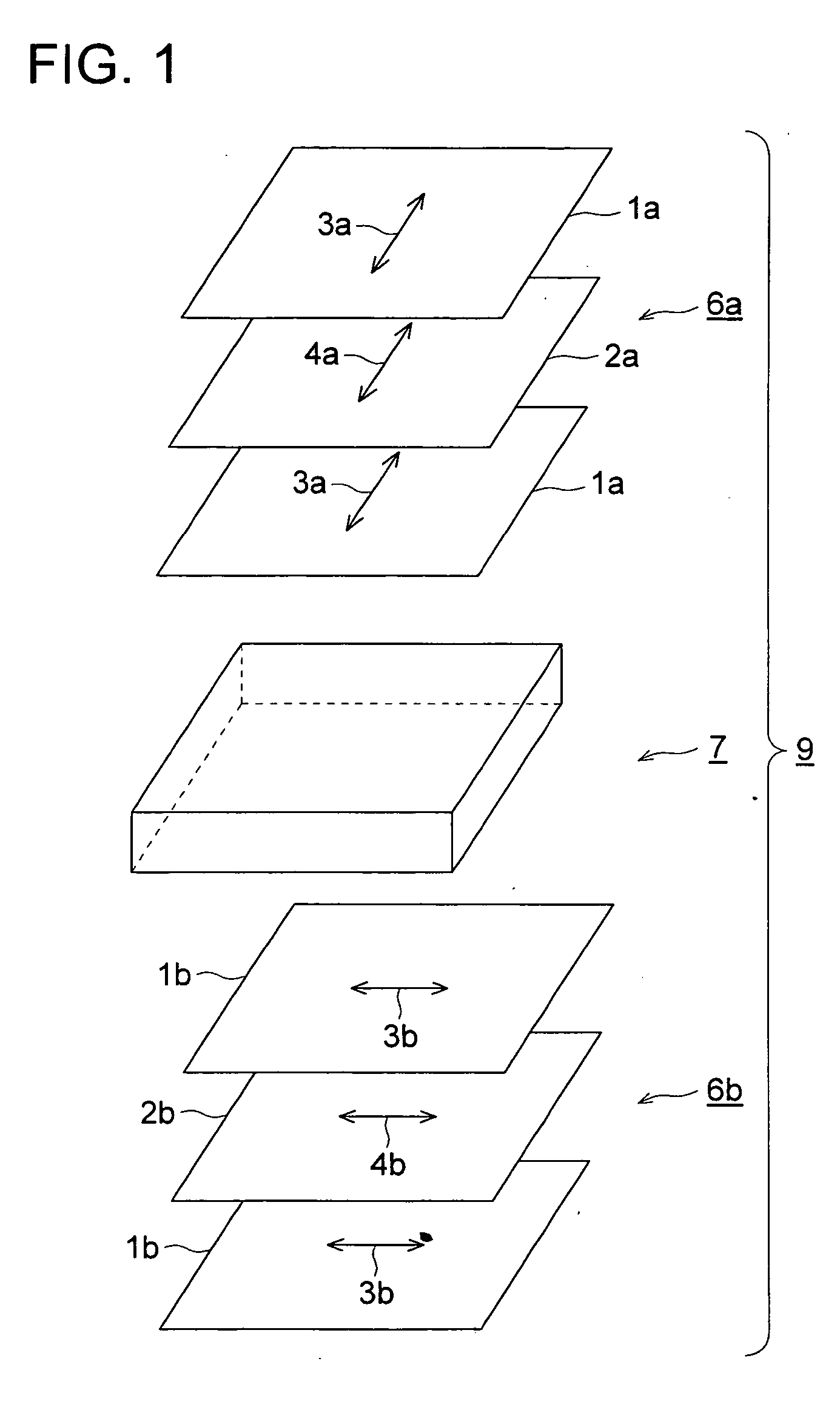
[0185] The polarizing plate of the invention has the constitution shown in, for example, FIG. 1. In FIG. 1, a liquid crystal display 9 is comprised of a crystal cell 7 and two polarizing plates 6a and 6b.
[0186] The polarizing plate 6a is comprised of two cellulose ester films 1a and one polarizing film 2a, and the polarizing plate 6b is comprised of two cellulose ester films 1b and one polarizing film 2b.

Problems solved by technology

Problem of the liquid crystal display is one in which a viewing angle is small.
However, this method could not prevent the thickness from increasing, although it is smaller in the thickness as compared with those in which a predetermined Rt is obtained by laminating plural conventional polarizing plate protective films.
However, a phase difference plate of a resin such as polycarbonate has problems in uniformity of phase difference or in transmittance, and is required to be laminated onto a polarizing plate every piece, which results in problems in productivity or cost of manufacture.
Further, when cellulose ester film is produced by dissolving cellulose ester and casting the resulting solution, cellulose ester in which the esterification has been insufficient tends to remain in the film as insoluble foreign materials.
When such a film is incorporated to a liquid crystal display element, the insoluble foreign materials causes defects that disturb the polarizing state to emit abnormal light due to its difference in the refractive index from cellulose ester film, so-called defects due to luminescent foreign materials.
These defects have been less problematic in a TN mode (TN-TFT) liquid crystal display, which is an optical rotatory mode, but it has been found that they are problems to be solved in a VA mode liquid crystal display, which is a birefringence mode.
However, when used in the VA mode liquid crystal display, any proposals described above are not satisfactory in view of resistance to heat and humidity, the number of foreign materials occurring or increase in viewing angle.

Method used


Image

  • Polarizing plate and liquid crystal display employing the same
  • Polarizing plate and liquid crystal display employing the same
  • Polarizing plate and liquid crystal display employing the same

Examples


example 1

>

(Preparation of Cellulose Ester Film 1)

[0189] Cellulose acetate propionate (with an acetyl substitution degree of 2.00 and a propionyl substitution degree of 0.80 and a viscosity average polymerization degree of 350) of 100 parts by weight, 5 parts by weight of ethylphthalylethyl glycolate, 3 parts by weight of triphenyl phosphate, 290 parts by weight of methylene chloride, and 60 parts by weight of ethanol were placed into a tightly sealed vessel, and gradually heated to 45° C. in 60 minutes while slowly stirred. Pressure in the vessel was 121 kpa. The resulting solution was filtered employing Azumi filter paper No. 244, produced by Azumi Roshi Co., Ltd., and allowed to stand for 24 hours to remove foams in the solution. Thus, a cellulose ester solution was prepared.

[0190] Five parts by weight of the cellulose acetate propionate described above, 6 parts by weight of TINUVIN 326 (produced by Ciba Specialty Co., Ltd.), 4 parts by weight of TINUVIN 109 (produced by Ciba Specialty ...

example 2

[0260] Polarizing plate samples 9 through 14 were prepared according to the following procedures:

9>>

(Preparation of Cellulose Ester Film TAC-A)

[0261] Cellulose ester film TAC-A was prepared according to the following procedures:

[0262] Cellulose triacetate (with an acetyl substitution degree of 2.92 and a viscosity average polymerization degree of 300) of 100 parts by weight, 2 parts by weight of ethylphthalylethyl glycolate, 8.5 parts by weight of triphenyl phosphate, 350 parts by weight of methylene chloride, and 50 parts by weight of ethanol were placed into a tightly sealed vessel, and gradually heated to 45° C. in 60 minutes while slowly stirred. Pressure in the vessel was 121 kPa. The resulting solution was filtered employing Azumi filter paper No. 244, produced by Azumi Roshi Co., Ltd., and allowed to stand for 24 hours to remove foams in the solution. Thus, a cellulose ester solution was prepared.

[0263] Five parts by weight of the cellulose triacetate described above, 3 ...


PUM

PropertyMeasurementUnit
Angleaaaaaaaaaa
Angleaaaaaaaaaa
Angleaaaaaaaaaa

Abstract

A polarizing plate used in a vertical alignment mode liquid crystal display comprising a liquid crystal cell is disclosed, wherein the polarizing plate comprises a polarizing film and a mixed fatty acid cellulose ester film with optical biaxiality provided between the polarizing film and the liquid crystal cell, and wherein the mixed fatty acid cellulose ester film has a retardation in plane R0 of from 31 to 120 nm, and a retardation in the thickness direction Rt of from 60 to 300 nm, in which R0 is represented by the following formula (1) and Rt is represented by the following formula (2): R0=(nx−ny)×d  formula (1) Rt={(nx+ny) / 2−nz}×d  formula (2)

Description

FIELD OF THE INVENTION [0001] The present invention relates to a polarizing plate employing as a protective film a film used for optical purposes having a phase difference function and a liquid crystal display employing the polarizing plate. BACKGROUND OF THE INVENTION [0002] A liquid crystal display operates at low voltage as well as low power consumption, and further, can be directly connected to an IC circuit. Specifically, it is possible to decrease its thickness. As a result, it is widely employed in word processors, personal computers, and the like, as the display. The basic structure of said liquid crystal display is such that polarizing plates are provided on the both sides of the liquid crystal cell. [0003] A liquid crystal display has characteristics in that it operates at low voltage as well as at low power consumption, and decreases its thickness, which other displays do not have. Problem of the liquid crystal display is one in which a viewing angle is small. Solution of...

Claims


Application Information

Patent Timeline
IPC IPC(8): G02F1/1335C08L1/14G02B5/30G02F1/13363G02F1/139
CPCC08L1/14G02B5/3033G02B5/3083G02F1/133634Y10T428/10G02F2001/133531Y10T428/105Y10T428/1036Y10T428/1041G02F1/1393C09K2323/00C09K2323/03C09K2323/031C09K2323/035G02F1/133531G02F1/13363
Inventor KUZUHARA, NORIYASUTASAKA, KOJIUMEDA, HIROKIYAJIMA, TAKATOSHI
Owner KONICA CORP
Learn More