
Passive dual-phase cooling for fuel cell assemblies

Inactive Publication Date: 2006-04-27
3M INNOVATIVE PROPERTIES CO
View PDF20 Cites 31 Cited by
  • Summary
  • Abstract
  • Description
  • Claims
  • Application Information

AI Technical Summary

Benefits of technology

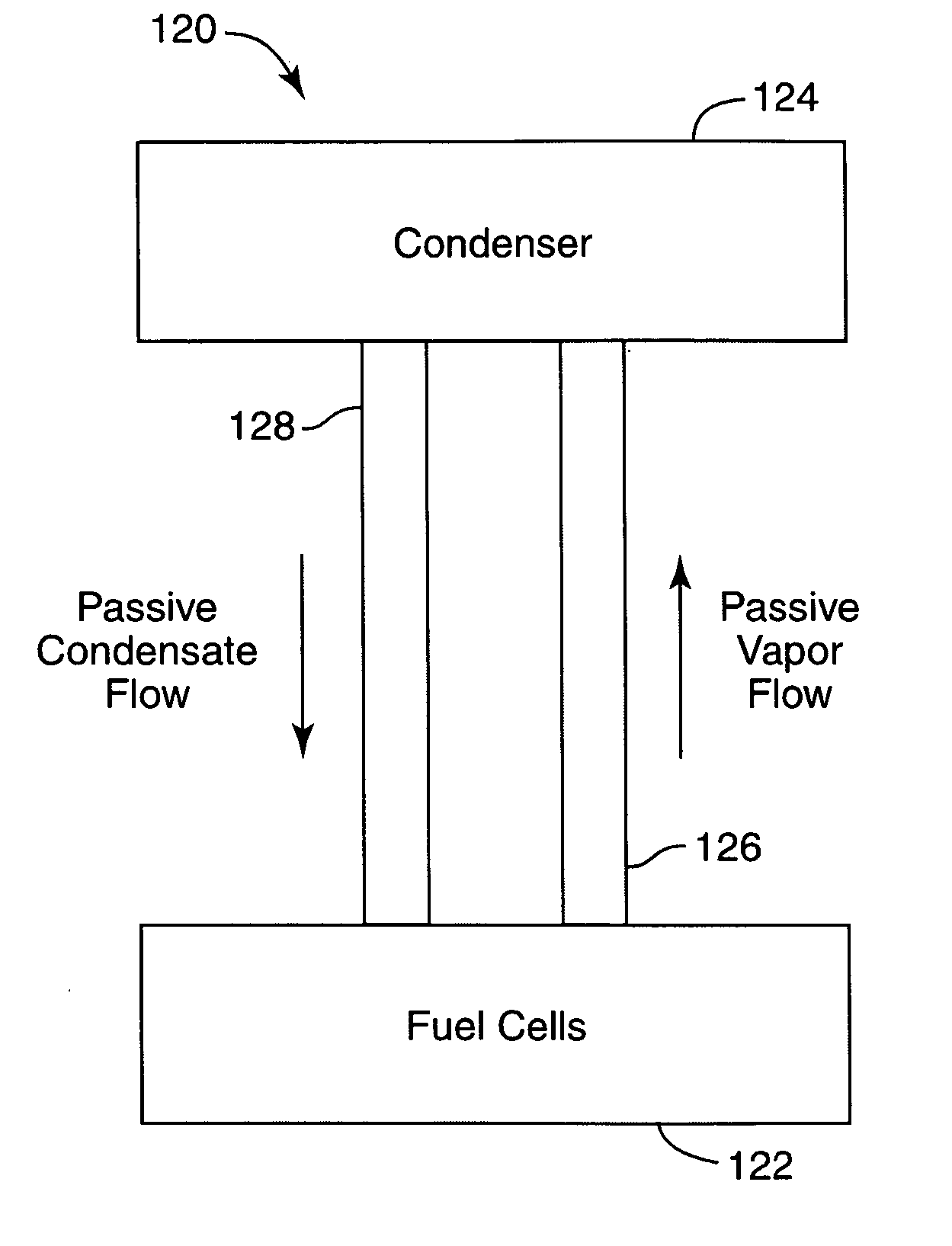
[0006] The present invention relates generally to passive dual-phase cooling arrangements and approaches for fuel cell components and assemblies within a fuel cell stack. More particularly, the present invention is directed to such passive dual-phase cooling apparatuses that incorporate surface coatings and / or features that effectively extend the critical heat flux of flow field plate coolant channels and / or improves temperature uniformity over the entire channel length while minimizing channel depth so as to reduce cooling plate thicknesses and reducing coolant requirements and weight. “Critical heat flux” means the heat flux beyond which boiling cannot be sustained because liquid no longer wets the surface. To “extend the critical heat flux” means increasing the value of heat flux beyond which boiling cannot be sustained because liquid no longer wets the surface. The present invention is further directed to such passive dual-phase cooling apparatuses that provide thermal management for fuel cell assemblies, stacks, and power systems that incorporate fuel cells.
[0008] The flow field plate includes a number of fluid flow channels that have a channel depth, a channel spacing, a channel length, and a channel width, the width of the channels being less than about 5 mm. The channel width, channel spacing, channel length, and channel depth are dimensioned in accordance with principles of the present invention to promote nucleated boiling of the heat transfer fluid below a critical heat flux and to prevent dryout as the heat transfer fluid passes along the length of the channels. In one implementation, the cooling apparatus maintains a maximum temperature gradient of less than about 0.2° C. / cm in a direction of heat transfer fluid flow as the MEA is subject to changes in heat flux to the heat transfer fluid from about 0 W / cm2 to about 1.5 W / cm2.

Problems solved by technology

Critical heat flux” means the heat flux beyond which boiling cannot be sustained because liquid no longer wets the surface.

Method used


Image

  • Passive dual-phase cooling for fuel cell assemblies
  • Passive dual-phase cooling for fuel cell assemblies
  • Passive dual-phase cooling for fuel cell assemblies

Examples


example

[0079] An apparatus shown generally in block diagram form in FIG. 2a was used to investigate parameters within a typical flow field coolant plate. This apparatus included a 7 inch by 20 inch aluminum heater plate 1 / 16″ thick into which a 4 inch by 15 inch recess 1 / 32 inch deep was machined to accommodate 5 flat, adhesive backed KAPTON heaters (Minco Model 5466, 3″ by 4″, nominal resistance 4.1 ohm, Minco Inc., Minneapolis Minn.). The remaining recess was filled with plasticiene clay. This back surface of the heater plate was mated to a 0.75 inch Plexiglas plate of the same dimensions. A thin layer of thermal interface grease (Wakefield Thermal Compound 120-2< Wakefield Engineering, Inc. Wakefield, Mass.) mated the front surface of this plate to the back of another 1 / 16″ aluminum channel plate. The back of this plate had 1 / 32 inch deep grooves into which 0.01 inch diameter type-T thermocouples were placed, terminating at the horizontal centerline and in vertical locations that corres...


PUM


Abstract

A cooling apparatus for a fuel cell assembly includes a heat transfer fluid and at least one fluid flow field plate configured to facilitate essentially passive, two-phase cooling for an membrane electrode assembly (MEA) as the MEA is subject to changes in heat flux to the heat transfer fluid from about 0 W / cm2 to about 1.5 W / cm2. The flow field plate includes fluid flow channels that have a channel depth, a channel spacing, a channel length, and a channel width, which are dimensioned to promote nucleated boiling of the heat transfer fluid below a critical heat flux and to prevent dryout as the heat transfer fluid passes along the length of the channels. The channels may include coatings and / or features, such as microporous or nanostructured coatings, that extend the critical heat flux and preclude dryout at the distal sections of the fluid flow channels.

Description

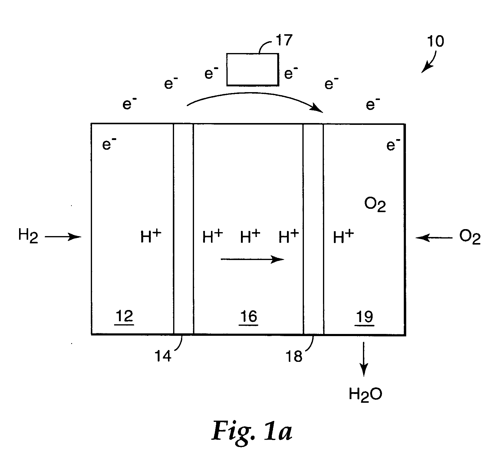
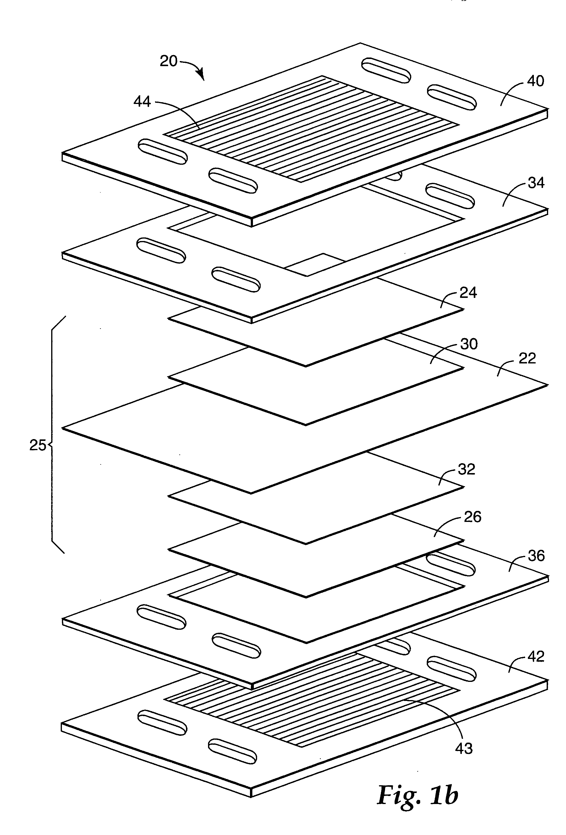
FIELD OF THE INVENTION [0001] The present invention relates generally to passive dual-phase cooling arrangements and approaches for fuel cell components and assemblies within a fuel cell stack. BACKGROUND OF THE INVENTION [0002] A typical fuel cell system includes a power section in which one or more fuel cells generate electrical power. A fuel cell is an energy conversion device that converts hydrogen and oxygen into water, producing electricity and heat in the process. Each fuel cell unit may include a proton exchange member at the center with gas diffusion layers on either side of the proton exchange member. Anode and cathode catalyst layers are respectively positioned at the inside of the gas diffusion layers. This type of fuel cell is often referred to as a PEM fuel cell. [0003] The reaction in a single fuel cell typically produces less than one volt. A plurality of the fuel cells may be stacked and electrically connected in series to achieve a desired voltage. Electrical curre...

Claims


Application Information

Patent Timeline
IPC IPC(8): H01M8/04H01M2/02
CPCH01M8/026H01M8/04029H01M8/04059H01M8/04074Y02E60/50H01M8/04B82Y30/00
Inventor TUMA, PHILLIP E.LEWINSKI, KRZYSZTOF A.DEBE, MARK K.
Owner 3M INNOVATIVE PROPERTIES CO
Learn More