
Method and converter circuitry for improved-performance AC chopper

a converter circuit and chopper technology, applied in the direction of power conversion systems, electric variable regulation, instruments, etc., can solve the problems of reducing the efficiency of power transmission, affecting the reliability of chopper, and affecting the performance of ac chopper, so as to increase the reliability, efficiency and flexibility of chopper, and simplify construction.

Inactive Publication Date: 2006-05-18
COMPULITE SYST 2000
View PDF2 Cites 73 Cited by
  • Summary
  • Abstract
  • Description
  • Claims
  • Application Information

AI Technical Summary

Benefits of technology

[0023] It is an object of the present invention to provide HF AC chopper circuitry that does not rely on deadtime and always provides a current path for the current of the inductor of the output filter, simplifying construction and increasing the reliability, efficiency and flexibility of the chopper for a variety of applications including lamp dimming and motor control.
[0024] It is another object of the present invention to eliminate the need for snubber capacitors in HF AC choppers to avoid large charging currents.
[0025] It is yet another object of the present invention to provide economical digital circuitry for improving the performance and ruggedness of HF AC choppers.

Problems solved by technology

Among these harmful effects are reduced efficiency of power transmission, possible interference to other devices connected to the power line and distortion of the waveform of the line voltage.
An earlier approach to dimmer design that was based on phase control, i.e. a low frequency chopper typically realized with SCR (Silicon Controlled Rectifier, or Thyristor) switches, has many deficiencies, including the fact that it injects a very high level of current harmonics into the line.
Among the disadvantages of the low-frequency chopper are the mechanical stress on lamp filaments when fed by low-frequency high-current pulses, and high peak current in the line that may blow fuses or trip circuit breakers.
Otherwise, very large and damaging voltage spikes develop.
However, prior-art HF AC chopper systems, such as the teaching of U.S. Pat. No. 5,500,575 and other publications, suffer from a basic problem that leads to the generation of high-voltage spikes and power losses, and hence, lower efficiency.
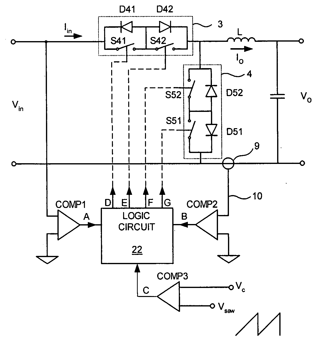
The problem stems from the need to leave a “deadtime” during which neither the series AC switch nor the AC switch (or diode-switch assembly) connected at the input terminals of the output filter are conductive.
During this deadtime the current of the output filter inductor is interrupted and a potentially damaging high-voltage spike develops.
This voltage might exceed the breakdown voltages of the active and passive elements of the circuit and cause irreversible damage to the system.
However, this capacitor causes large current spikes and losses in the series AC switch.
The voltage difference between the input voltage and the capacitor voltage causes high charging current, limited only by the parasitic resistances of the line and switch.
It is thus evident that the prior art has failed to provide a remedy for the problem of the deadtime in HF AC choppers.
Prior art teachings do not adequately address this issue but, rather, assume that when the HF AC chopper operates in “open loop” (with respect to the input current), the input current is automatically of low harmonic content.
This causes a distortion of the input current and prior-art solutions fail to provide a remedy for this problem, too.
It is thus evident that prior-art teachings fail to provide solutions to many problems associated with the design of a HF AC chopper.

Method used


Image

  • Method and converter circuitry for improved-performance AC chopper
  • Method and converter circuitry for improved-performance AC chopper
  • Method and converter circuitry for improved-performance AC chopper

Examples


Embodiment Construction

[0069] The present invention is of a HF AC chopper which can be used to control delivery of power to a load. Specifically, the present invention can be used to provide an AC voltage that is less than the powerline voltage and is of substantially sinusoidal waveform to a load. The load can be resistive or reactive, and the current drawn from the power line is substantially sinusoidal and has minimal harmonic content.

[0070] The principles and operation of a HF AC chopper according to the present invention may be better understood with reference to the drawings and the accompanying description.

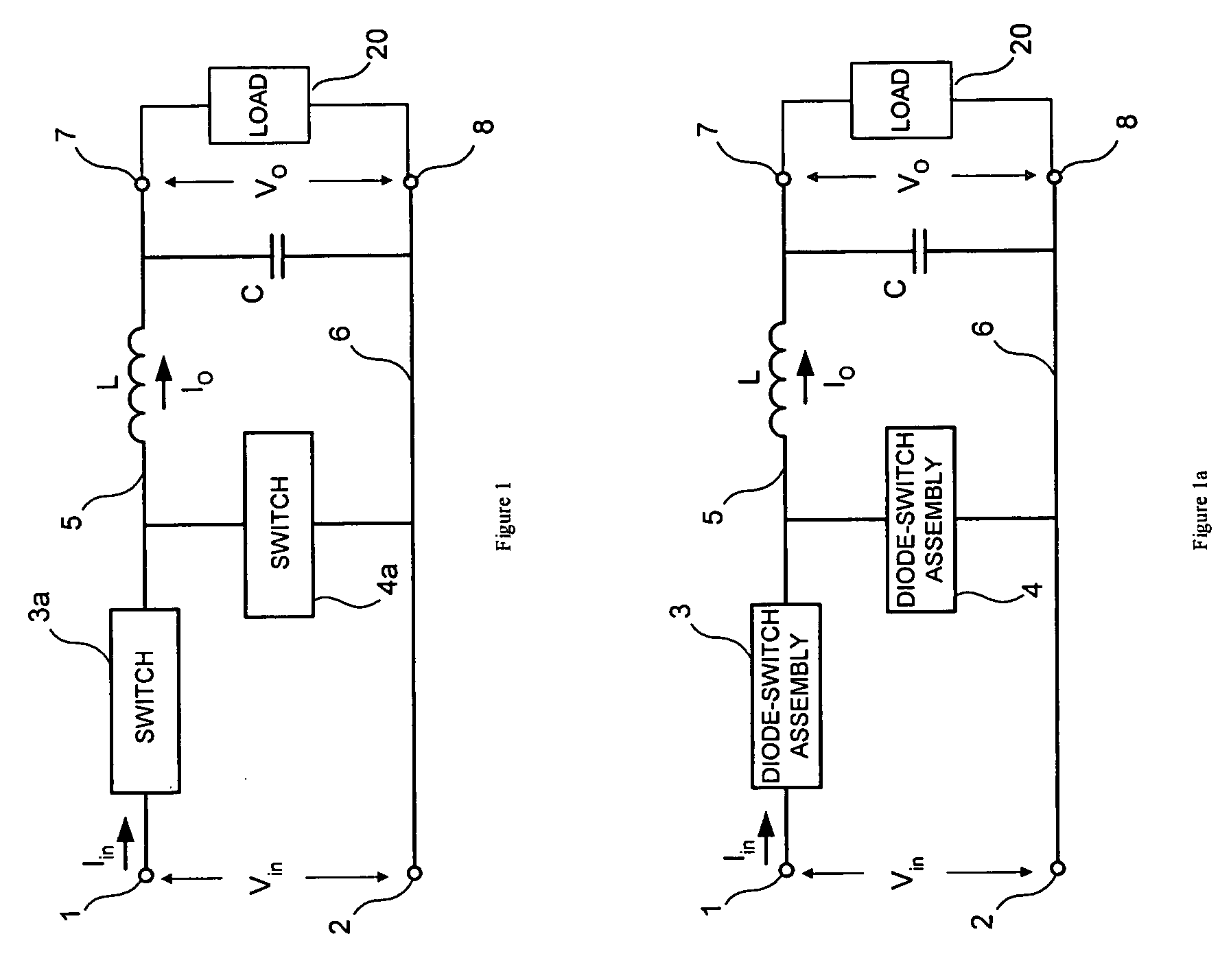
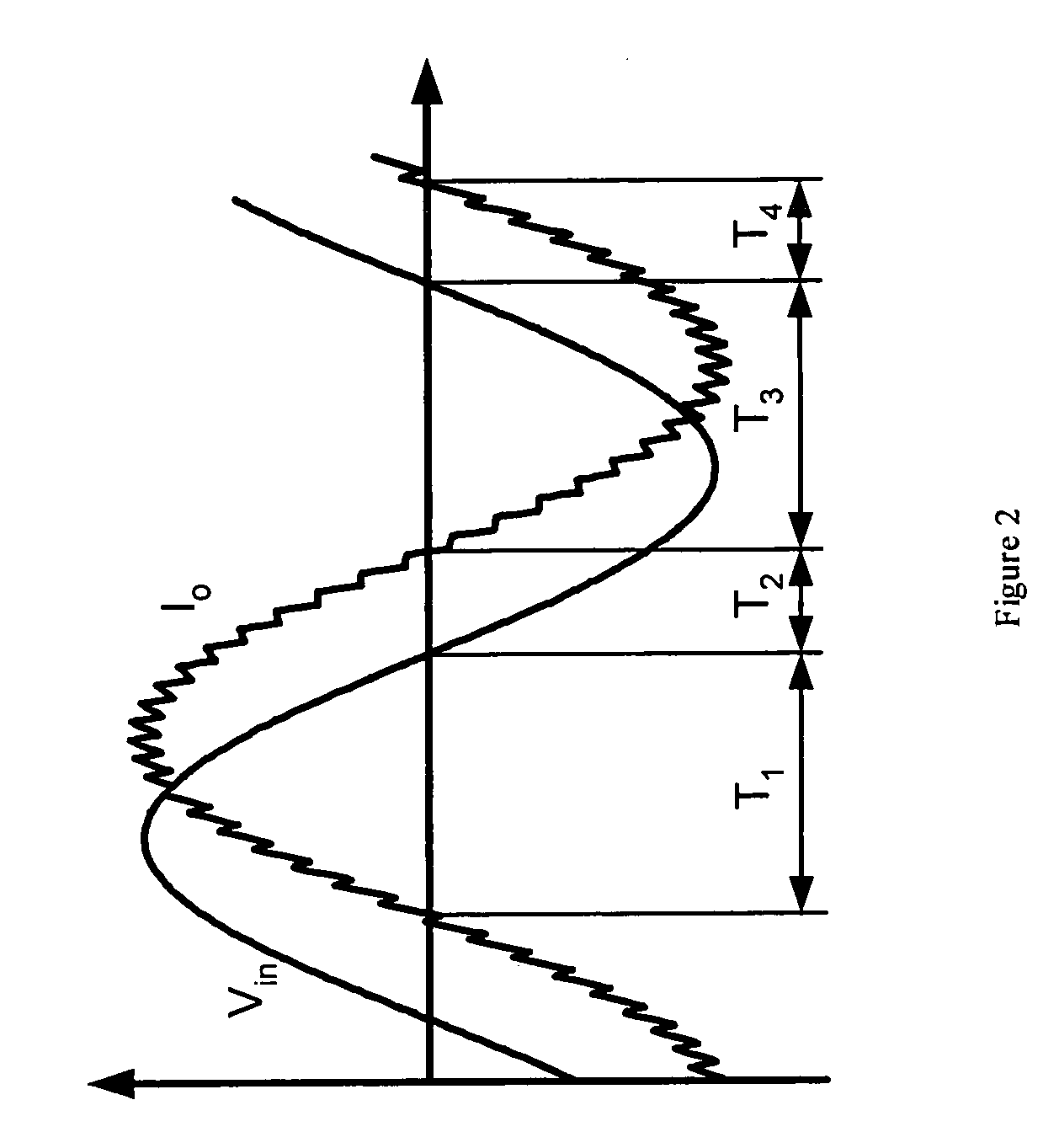
[0071] Referring now to the drawings, FIG. 1a illustrates a generic embodiment of the power stage of a HF AC chopper according to the present invention. FIG. 2 illustrates schematically voltage and current waveforms associated with the chopper. FIG. 3 illustrates, schematically, operational modes, or regimes, corresponding to portions of the waveforms depicted in FIG. 2. The power stage depicte...


PUM


Abstract

A system and method for single phase AC power conversion for delivery to a load of AC voltage less than or equal to the supply voltage. The system includes a high frequency chopper converter having a series diode-switch assembly and a shunt diode-switch assembly. During intervals when the inductor carries current in phase with the power line, the diode-switch assemblies are configured such that the system operates as a buck converter, and during intervals when the inductor carries current out of phase with the power line, and power flow is reversed, the diode-switch assemblies are configured such that the system operates as a boost converter, boosting the load voltage to the power line voltage. Optionally, feedback is used to adjust the duty cycles of the diode-switch assemblies to shape the input and / or output current and to optimize performance of the load.

Description

FIELD AND BACKGROUND OF THE INVENTION [0001] The present invention relates to a switching power converter and, more particularly, to a method and circuitry for converting an alternating-current (AC) power line voltage into a lower AC voltage while drawing from the line a current of proportionally lower amplitude. [0002] The prior art includes several types of converters, which are widely used for DC(direct current)-to-DC, DC-to-AC, AC-to-DC and AC-to-AC power conversion. In some applications the purpose of the converter is to provide a regulated output voltage. In other applications, the purpose of the power conversion schemes is attenuating the voltage of an AC source, such as a power line, while maintaining the waveform of the line voltage. For example, in a power converter known in the art as an AC Chopper, the role of the converter is to supply to a load an AC voltage lower than the voltage of the AC source. This is accomplished by introducing an AC (bidirectional) switch betwee...

Claims


Application Information

Patent Timeline
IPC IPC(8): G05F3/16
CPCH02M5/293
Inventor BEN-YAACOV, SHMUEL
Owner COMPULITE SYST 2000
Learn More