Large mode area fibers using higher order modes

a fiber and higher-order technology, applied in the field of optical fiber devices, can solve the problems of low mode coupling performance of fibers, and achieve the effects of large mode area, good bend loss performance, and large spacing

Active Publication Date: 2006-05-18
FURAKAWA ELECTRIC NORTH AMERICA INC
View PDF3 Cites 77 Cited by
  • Summary
  • Abstract
  • Description
  • Claims
  • Application Information

AI Technical Summary

Benefits of technology

[0012] We have developed a new approach to the realization of optical fiber devices with very large mode area, good bend loss performance, large spacing between guided modes (for low mode coupling), and good beam quality (M2˜1). These properties are produced, according to the invention, by using a few mode optical fiber, and converting the input signal to a higher order mode. This yields significant design flexibility, so that all the desirable properties (large Aeff, low bend loss, low mode coupling and M2˜1) can be simultaneously achieved.
[0014] The first design class (called the ring design, henceforth) illustrates a fiber with a central core and one or more high index rings followed by a down-doped region. The second design class (called the truncated cladding design, henceforth) comprises a central core and an inner cladding, followed by a broad down-doped region spaced significantly from the center of the fiber. Both of these designs can yield Aeff for the LP02 mode ranging up to 2800 μm2 and beyond. Furthermore, the deep-down-doped regions ensure that the HOM is not radiated, and thus good bend loss performance is obtained. The enhanced design flexibility for HOM fibers enables designing them with large effective index separations (Δneff—the difference in effective index between the LP02 mode and any other guided mode). Designs guiding the LP12 mode in addition to the desired LP02 mode yield Δneff>8×10⁻⁵, while designs that guide only the LP01, LP11, and LP02 modes yield Δneff as high as 3×10⁻³. Thus, these fibers exhibit very low mode coupling problems. In addition, the LP02 mode is vastly spatially separated from other guided modes in the fiber. Thus, preferential gain-guiding mechanisms attempted earlier for fundamental mode gain fibers, can be readily applied here to further increase modal discrimination and decrease the deleterious effects of mode mixing. Another advantage of these fibers is that while the signal propagates in the LP02 mode, light enters / exits the fiber in the fundamental, LP01 mode. The characteristics of this mode are governed by the central core, while those of the LP02 mode are governed by other features. Hence, the central core can be designed to yield a LP01 mode with mode profile almost indistinguishable from a perfect Gaussian mode profile.
[0016] Since signal propagation is in the LP02 mode rather than the fundamental mode, the fiber is provided with mode-converters to convert the incoming signal in the fundamental mode, into the HOM. The output signal may either be down-converted to the LP01, mode, or focused / collimated as is. Mode converters also function as wavelength selective filters, such as a bandpass filter. These are useful for filtering out unwanted ASE r stokes shifted light. Thus, use of HOMs is advantageous even if Aeff is not large.

Problems solved by technology

Thus, these fibers exhibit very low mode coupling problems.

Method used


Image

  • Large mode area fibers using higher order modes
  • Large mode area fibers using higher order modes
  • Large mode area fibers using higher order modes

Examples


Embodiment Construction

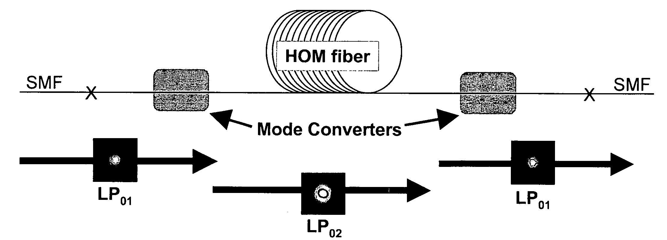
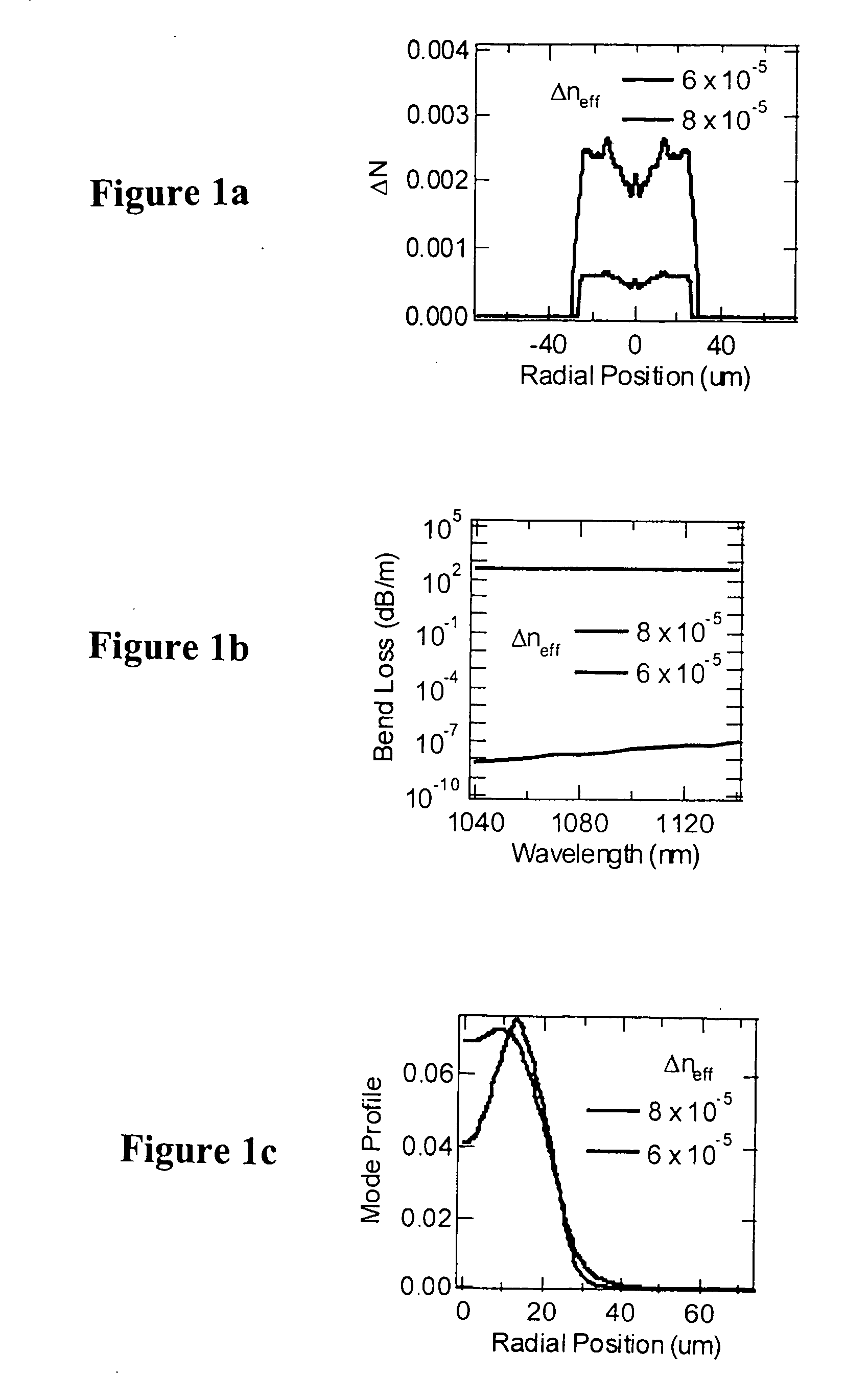
[0029] As mentioned previously, two distinct embodiments of fiber designs suitable for the gain section of the devices of the invention will be described. These are illustrative of optical fibers wherein the HOM is the LP02 mode, but the invention can be implemented with any HOM guided by the fiber. It should also be understood that other optical fiber designs may be found useful for obtaining the high effective area performance demonstrated by the two designs shown here. These optical fibers are examples of a category of optical fibers known as few mode fibers. They have a mode field larger than a single mode fiber.

[0030] The ring design optical fiber has a central core and one or more high index rings (with Δn>2×10⁻³) of thickness greater than 2 μm, followed by a deep down doped region (Δn40 μm. For designs utilizing the wavelength selectivity of mode converters, this invention is advantageous even with small (6-10 μm) MFD fiber.

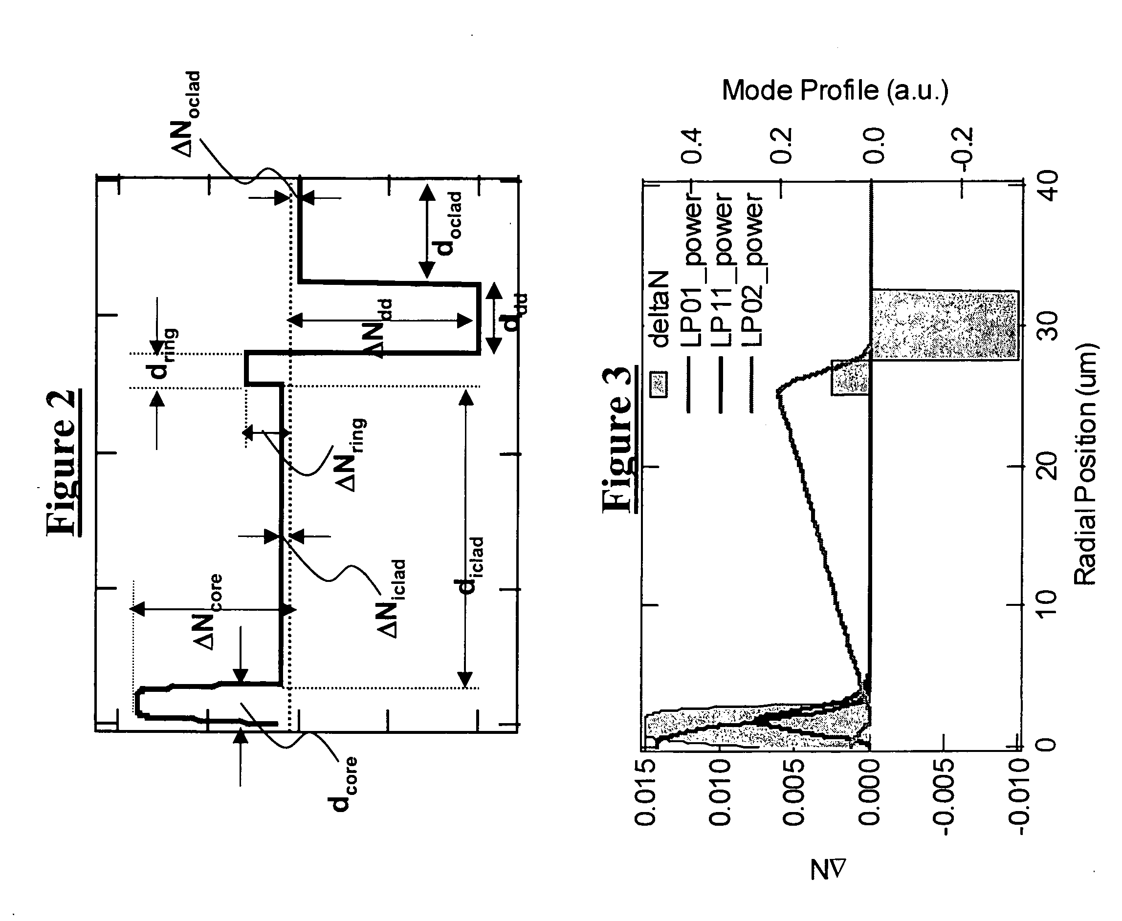
[0031]FIG. 2 shows the canonical refractive index ...


PUM


Abstract

The specification describes an optical fiber device wherein a LOM is converted to an HOM prior to entering the gain section. The gain section is a few mode fiber that supports the HOM. The output from the gain section, i.e. the HOM, may be utilized as is, or converted back to the LOM. With suitable design of the few mode fiber in the gain section of the device, the effective area, Aeff, may be greater than 1600 μm2. The large mode separation in the gain section reduces mode coupling, allowing greater design freedom and reducing the bend sensitivity of the optical fiber.

Description

FIELD OF THE INVENTION [0001] This invention relates to optical fiber devices, such as lasers and amplifiers, that produce high power levels through the use of large effective mode area. More specifically, the devices derive improved performance characteristics when the gain element is deliberately operated in a higher order mode. BACKGROUND OF THE INVENTION [0002] (Parts of the following section may not be prior art.) [0003] Fiber lasers with high pulse energy, good beam quality and excellent optical characteristics have applications in many fields and industries such as materials processing (marking, welding, semiconductor wafer and mask repair etc), medical and industrial spectroscopy (fluorescence, absorption), illumination, remote sensing and spectroscopy (wind speed, biohazards, ecosystem mapping etc), ranging and targeting (collision avoidance, military applications etc) and scientific instrumentation. For reasons of simplicity and efficiency, Yb3+-doped fibers are most commo...

Claims


Application Information

Patent Timeline
Patent Type & Authority Applications(United States)
IPC IPC(8): H04B10/12G02B6/26
CPCG02B6/02019G02B6/02023G02B6/02047G02B6/03611G02B6/0365G02B6/03666G02B6/14H01S3/06708H01S3/06729H01S3/0675H01S3/06754H01S3/08022H01S3/094007
Inventor DIGIOVANNI, DAVID J.RAMACHANDRAN, SIDDHARTH
Owner FURAKAWA ELECTRIC NORTH AMERICA INC
Why Eureka
Try Eureka