Ceramic honeycomb structure, process for producing the same and coat material for use in the production

Active Publication Date: 2006-05-18
HITACHI METALS LTD
View PDF3 Cites 38 Cited by
  • Summary
  • Abstract
  • Description
  • Claims
  • Application Information

AI Technical Summary

Benefits of technology

[0016] Accordingly, an object of the present invention is to provide a ceramic honeycomb structure having such exce

Problems solved by technology

However, in the case of producing large ceramic honeycomb structures of 150 mm or more in outer diameter and 150 mm or more in height for diesel engines, and thin honeycomb structures with cell walls 4 as thin as 0.2 mm or less, for instance, the green bodies are too heavy or insufficient in strength to support themselves, causing the problem that the cell walls 4 near the peripheral wall 3 are collapsed or deformed.
It has been found, however, that when the ceramic honeycomb structures described in Japanese Patents 2,604,876 and 2,613,729 are used for catalytic converters for cleaning an exhaust gas and filters for capturing particulates, there arise the following problems.
Because a high-temperature exhaust gas flows through a larger number of flow paths in the ceramic honeycomb structure, rapid temperature elevation locally occurs particularly at the time of starting operation, causing temperature difference between the center portion and the peripheral wall layer of the ceramic honeycomb body, and thus generating thermal stress in the ceramic honeycomb structure, which sometimes leads to cracking in the peripheral wall layer.
Also, when used as a particulate-capturing filter, local temperature elevation occurs particularly near the center portion of the honeycomb structure in which a large amount of particulates are accumulated, by heat generated by a regeneration treatment for burning particulates accumulated in the filter, resulting in cracking in the peripheral wall layer by thermal stress.
If cracking occurs in the peripheral wall layer and propagates to the cell walls, the cell walls are detached, resulting in decrease in the performance of cleaning an exhaust gas, and also decrease in a particulates-capturing rate because of the communication of flow paths between the inlet and outlet.
When a large hon

Method used


Image

  • Ceramic honeycomb structure, process for producing the same and coat material for use in the production
  • Ceramic honeycomb structure, process for producing the same and coat material for use in the production
  • Ceramic honeycomb structure, process for producing the same and coat material for use in the production

Examples


first embodiment

[1] First Embodiment

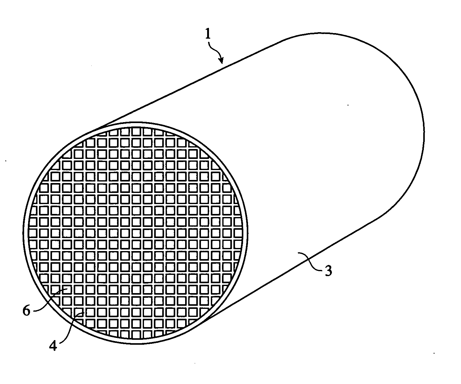
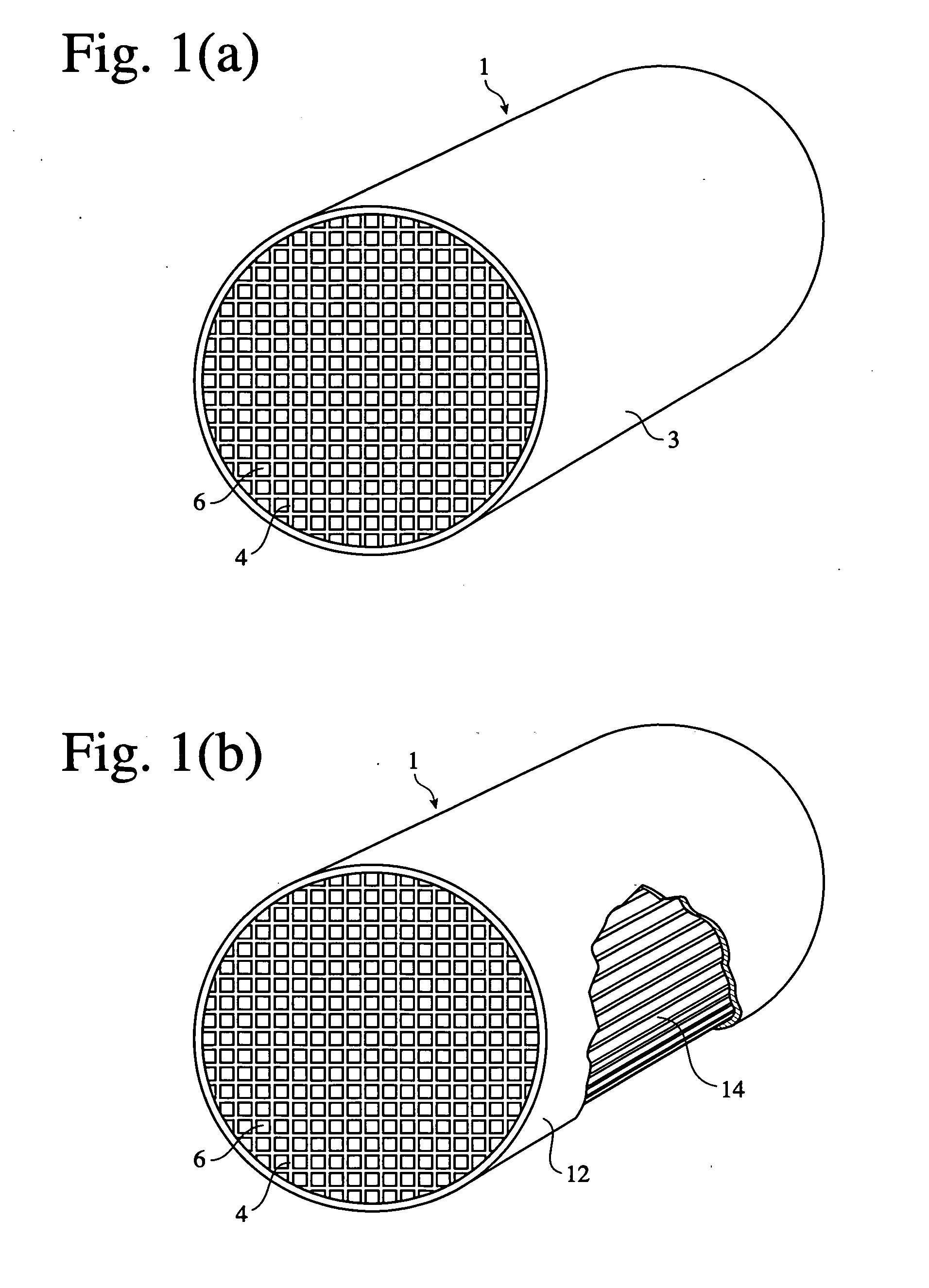
[0056] The ceramic honeycomb structure according to the first embodiment comprises a ceramic honeycomb body having grooves axially extending on its outer surface and cell walls constituting a large number of flow paths inside the grooves, and a peripheral wall layer covering the grooves, the ceramic honeycomb body comprising stress release portions at least in a portion of the peripheral wall layer and / or in a portion between the peripheral wall layer and the grooves. The stress release portions drastically improve the thermal shock resistance of the honeycomb structure. When the ceramic honeycomb structure is rapidly heated by an exhaust gas, the stress release portions function to prevent thermal shock from accumulating in the peripheral wall layer, thereby making it unlikely that cracking occurs in the peripheral wall layer, and that even if cracking occurred, it would not propagate into cell walls. The cell walls are thus kept from falling, causing no decreas...

second embodiment

[2] Second Embodiment

[0066] The ceramic honeycomb structure according to the second embodiment comprises a ceramic honeycomb body having grooves axially extending on its outer surface and cell walls constituting a large number of flow paths inside the grooves, and a peripheral wall layer covering the grooves, a thermal expansion coefficient of the peripheral wall layer being smaller than those of the cell walls in a radial direction. When the peripheral wall layer made of a coating material having a smaller thermal expansion coefficient than those of the cell walls is cooled to room temperature after drying or firing, a compressive stress remains in the peripheral wall layer, while a tensile stress remains in the cell walls, because of the difference in a thermal expansion coefficient between the cell walls and the peripheral wall layer. Therefore, even if the ceramic honeycomb structure has a higher temperature in a center portion than in a peripheral wall layer particularly at the...

third embodiment

[3] Third Embodiment

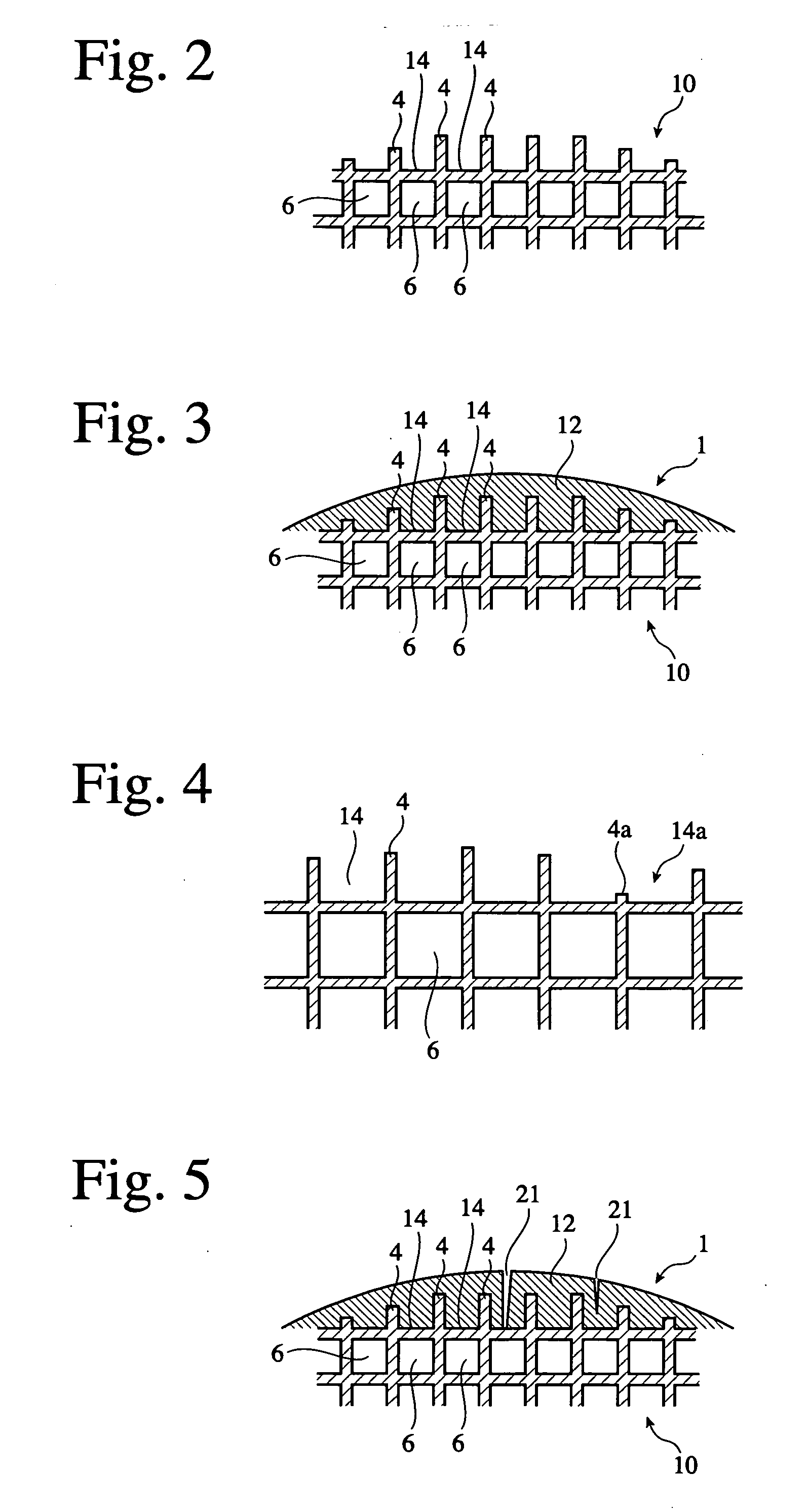
[0077] In the third embodiment, the peripheral wall and the nearby cell walls of the honeycomb green body is removed before firing. Because the peripheral wall and the cell walls have high hardness after firing, the cutting of the peripheral wall and the nearby cell walls is likely to cause chipping in the cell walls and takes a lot of time. On the other hand, because the peripheral wall and the cell walls are easily cut because of low hardness before firing, the removal of the peripheral wall and the nearby cell walls by cutting can be carried out in a short period of time without chipping in the cell walls.

[0078] When the peripheral wall 3 is removed from the dried green body having a honeycomb structure, the cell walls 4 are resistant to chipping 4a during removing the peripheral wall 3 of the fired body, thereby sufficiently keeping an contact area between the cell walls 4 and the peripheral wall layer 12. Further, when the peripheral wall 3 is removed at th...


PUM

PropertyMeasurementUnit
Fractionaaaaaaaaaa
Pore sizeaaaaaaaaaa
Percent by massaaaaaaaaaa

Abstract

A ceramic honeycomb structure comprising a ceramic honeycomb body comprising axial grooves on its periphery and cell walls constituting a larger number of flow paths inside the grooves, and a peripheral wall layer covering the grooves, wherein there are stress release portions at least partially in the peripheral wall layer and/or between the peripheral wall layer and the grooves. The thermal expansion coefficient of the peripheral wall layer is preferably smaller than those of the cell walls in a radial direction. The peripheral wall layer is preferably formed on the ceramic honeycomb body formed by removing a peripheral wall from a ceramic green body, before or after firing the ceramic honeycomb body.

Description

FIELD OF THE INVENTION [0001] The present invention relates to a ceramic honeycomb structure with a peripheral wall layer, which neither suffers from cracking nor peels off from a honeycomb body, and its production method. It particularly relates to a ceramic honeycomb structure having sufficient mechanical strength to avoid cracking, chipping, etc. by vibration, etc., when used in exhaust gas-cleaning catalytic converters or in particulates-capturing filters, which are likely to be subjected to thermal shock at high temperatures, and a production method thereof. BACKGROUND OF THE INVENTION [0002] From the aspect of protecting the environment not only in local areas but also in the entire globe, exhaust gas-cleaning catalytic converters and particulates-capturing filters with ceramic honeycombs are used to remove harmful substances such as carbon particulates, etc. from exhaust gases emitted from diesel engines. As shown in FIG. 1, a honeycomb structure I integrally comprises a peri...

Claims


Application Information

Patent Timeline
IPC IPC(8): B32B3/12B01D46/00B01D46/24B01D53/88B01J35/04F01N3/28
CPCB01D46/0001Y10T428/24165B01D46/2425B01D46/2429B01D46/2444B01D46/2451B01D46/2455B01D46/2466B01D46/2474B01D53/885B01D2046/2433B01D2046/2437B01D2046/2492B01D2046/2496B01J35/04F01N3/2828F01N2260/10F01N2330/06F01N2330/30Y10T428/24744Y10T428/24149Y10T428/24157Y10T428/24777Y10T428/254B01D46/2418C04B41/85C04B41/009C04B41/508C04B41/5089C04B2111/00793C04B2111/0081Y10T428/249953B01D46/2486B01D46/24492B01D46/24491B01D46/2498B01D46/2482B01D46/24494C04B41/5024C04B41/53C04B41/5035C04B35/195C04B38/0006B01D46/2462
Inventor SUWABE, HIROSHIAOTSUBO, YASUHIKOKIMURA, TOSHIAKI
Owner HITACHI METALS LTD
Why Eureka
Try Eureka