Production method for tubular carbon molecule and tubular carbon molecule, production method for recording device and recording device, production method for field electron emission element and field electron emission element, and production method for display unit and display unit

a production method and technology for carbon atoms, which are applied in the manufacture of electrode systems, electric discharge tubes/lamps, and discharge tubes luminescent screens, etc., can solve the problems of only achieving mass productivity with photolithography, and not being suitable for forming a three-dimensional structure such as the carbon nanotube structure,

Inactive Publication Date: 2006-05-25
SONY CORP
View PDF8 Cites 33 Cited by
  • Summary
  • Abstract
  • Description
  • Claims
  • Application Information

AI Technical Summary

Benefits of technology

[0022] It is a fifth object of the invention to provide a method of manufacturing a display unit capable of mass-producing fine-pitch display units which can clearly display a higher-definition image through the use of a field electron emission device including a cathode in which a tubular carbon molecule is regularly aligned with a finer spacing, and a display unit obtained by the method.

Problems solved by technology

However, in the structure, it is difficult to dispose the cathode panel and the anode panel at a close distance, so it is necessary to apply a high voltage between the cathode panel and the anode panel.
However, conventionally, photolithography is the only technique which can achieve mass productivity to some extent.
Photolithography is a technique basically suitable for forming a two-dimensional structure, so photolithography is not suitable for forming a three-dimensional structure such as the carbon nanotube structure.
Moreover, in order to form a fine pattern of a metal catalyst by photolithography, there is no way but to reduce the wavelength of an energy beam, and in the present technique, it is difficult to further reduce the wavelength.
In other words, there is a problem that the conventional technique has a limit of forming a finer pattern of a metal catalyst or the like.
Further, in a cathode using a conventional carbon nanotube, a large number of carbon nanotubes are closely disposed, so there is a problem that an electric field strength on the surface of each carbon nanotube pronouncedly declines.
Therefore, in order to increase the electric field strength on the surface of the carbon nanotube, it is necessary to apply a high voltage between a cathode electrode and an extraction electrode or an anode electrode, so it is difficult to lower the voltage.
In addition, conventionally, the shapes and growth directions of a large number of carbon nanotubes constituting the cathode are not uniform, so the amount of emitted electrons are not uniform, thereby there is a problem that variations in intensity occurs.

Method used


Image

  • Production method for tubular carbon molecule and tubular carbon molecule, production method for recording device and recording device, production method for field electron emission element and field electron emission element, and production method for display unit and display unit
  • Production method for tubular carbon molecule and tubular carbon molecule, production method for recording device and recording device, production method for field electron emission element and field electron emission element, and production method for display unit and display unit
  • Production method for tubular carbon molecule and tubular carbon molecule, production method for recording device and recording device, production method for field electron emission element and field electron emission element, and production method for display unit and display unit

Examples


first embodiment

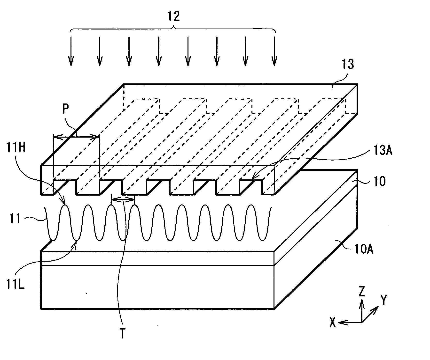
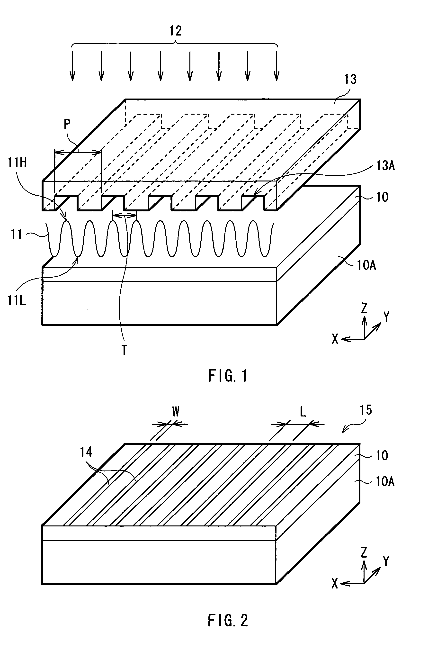
[0110] At first, referring to FIGS. 1 through 3, a method of manufacturing a tubular carbon molecule according to a first embodiment of the invention will be described below. In the method according to the embodiment, a carbon nanotube structure including a plurality of carbon nanotubes aligned in one direction is formed, and the method according to the embodiment includes “a catalyst arranging step” of arranging a metal having a catalyst function for a carbon nanotube through the use of melting by a modulated heat distribution, and “a growing step” of growing a carbon nanotube through the use of the metal having a catalyst function. The obtained carbon nanotube structure is used as, for example, a cathode of an FED or a recording apparatus.

[0111] In this case, the carbon nanotube structure includes various modes such as a carbon nanotube structure in which a plurality of carbon nanotubes are aligned in a fine pattern, a carbon nanotube structure in which a foreign material is incl...

second embodiment

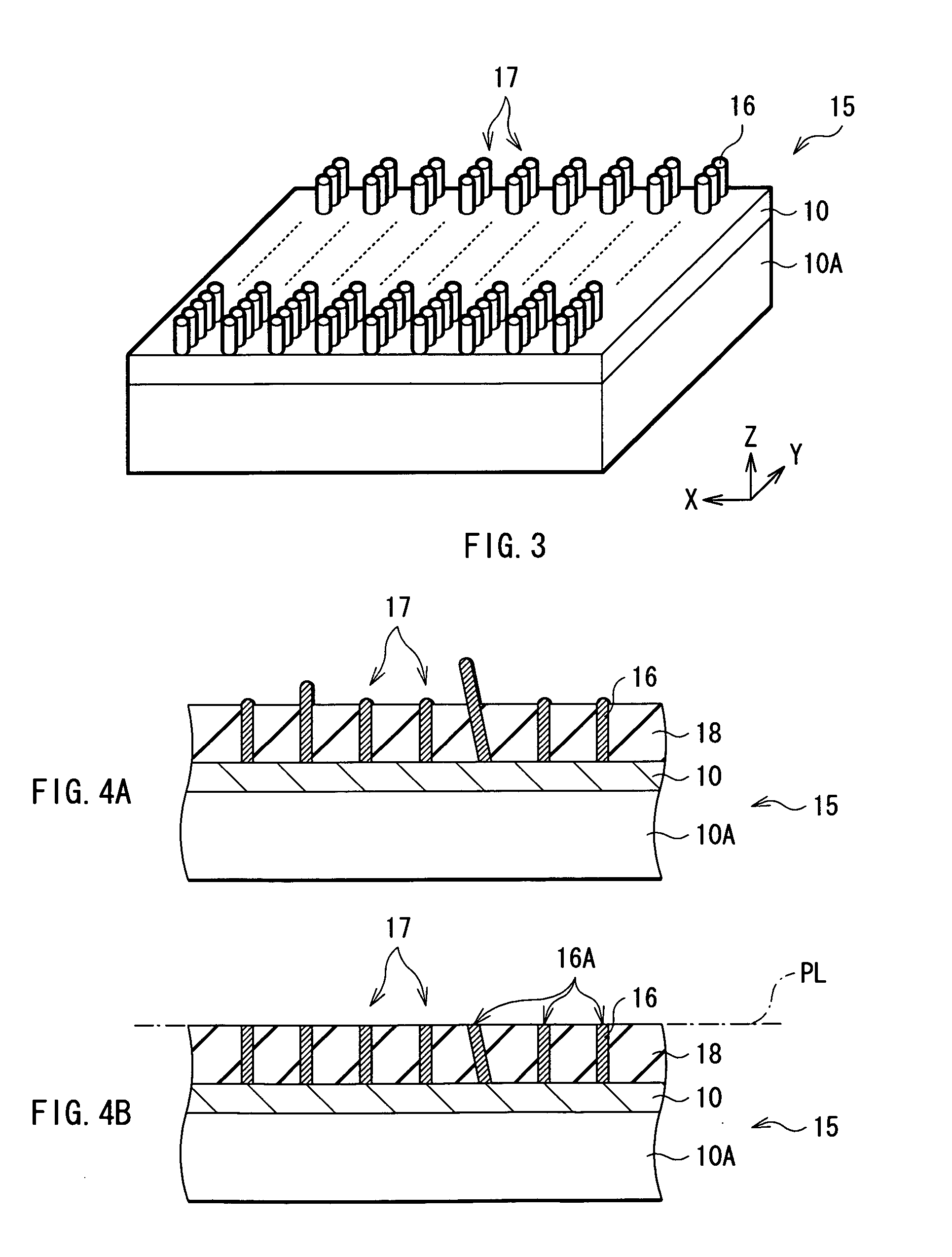
[0136] Next, a second embodiment of the invention will be described below. The embodiment further includes a height equalizing step of forming tips of the carbon nanotubes 16 in a predetermined plane after the carbon nanotube structure 17 is formed according to the first embodiment, and forming the tips into open tips (open ends).

[0137] In the embodiment, “height” means the position of the tip of the carbon nanotube 16, that is, a distance between the surface of the material substrate 10 and the tip of the carbon nanotube 16. Therefore, the height of the carbon nanotube 16 may be different from the length of the carbon nanotube 16, that is, an actual dimension in an extending direction.

(Height Equalizing Step)

[0138] The height equalizing step will be described below referring to FIGS. 4A and 4B. At first, as shown in FIG. 4A, a fixing layer 18 is formed around the carbon nanotubes 16 to fix the carbon nanotubes 16 by the fixing layer 18. As the material of the fixing layer 18, f...

third embodiment

[0143] Next, a method of manufacturing a carbon nanotube according to a third embodiment of the invention will be described below. In the method according to the embodiment, a desired material is included in tip portions of the carbon nanotubes 16 in the growing step in the first embodiment. The obtained carbon nanotube structure 17 can be used for various uses, for example, depending upon the included material, and in the embodiment, a magnetic material, for example, iron is included so that the carbon nanotube structure 17 can be used as a recording apparatus.

[0144] As a method of including a desired material at the time of growing the carbon nanotubes 16, a VLS (Vapor-Liquid-Solid) method which is a kind of the CVD method can be used. The VLS method uses an effect that a gas including carbon is decomposed to form alloy drops including carbon and a metal having a catalyst function, and carbon nanotubes 16 are grown on the alloy drops in one direction. In the VLS method, as the ca...


PUM

PropertyMeasurementUnit
thicknessaaaaaaaaaa
surface roughnessaaaaaaaaaa
widthaaaaaaaaaa

Abstract

A method of manufacturing a tubular carbon molecule capable of regularly aligning a carbon nanotube with a finer spacing is provided. A catalyst is arranged on a material substrate (10) made of a semiconductor such as silicon (Si) and including iron (Fe) as a catalyst through the use of melting according to a modulated heat distribution (11). The heat distribution (11) is formed, for example, through diffracting an energy beam (12) by a diffraction grating (13). As a method of arranging the catalyst, for example, iron may be deposited in a planar shape or a projection shape in a position corresponding to the heat distribution (11), or the deposited iron may be used as a master to be transferred to another substrate. A carbon nanotube is grown through the use of the arranged catalyst. The grown carbon nanotube can be used as a recording apparatus, a field electron emission device, an FED or the like.

Description

TECHNICAL FIELD [0001] The present invention relates to a method of manufacturing a tubular carbon molecule capable of aligning a tubular carbon molecule such as a carbon nanotube in a fine pattern, and a tubular carbon molecule obtained by the method. Moreover, the invention relates to a method of manufacturing a recording apparatus and a recording apparatus which uses the tubular carbon molecule, a method of manufacturing a field electron emission device including a cathode which uses the tubular carbon molecule, and a field electron emission device obtained by the method, and a method of manufacturing a display unit and a display unit which uses the field electron emission device. BACKGROUND ART [0002] In recent years, nanotechnology has made considerable strides recently, and in particular, a molecular structure such as a carbon nanotube is a stable material having superior properties such as high thermal conductivity, high electrical conductivity and high mechanical strength, s...

Claims


Application Information

Patent Timeline
Patent Type & Authority Applications(United States)
IPC IPC(8): H01J1/02C01B31/02H01J1/304H01J9/02
CPCB82Y10/00B82Y30/00B82Y40/00C01B31/0233H01J1/304H01J9/025H01J2201/30469H01J2329/00C01B32/162
Inventor GOSAIN, DHARAM PALKAJIURA, HISASHIMARUYAMA, RYUICHIROSHIRAISHI, MASASHIHUANG, HOUJINKADONO, KOJIWACHI, SHIGEAKIATA, MASAFUMI
Owner SONY CORP
Why Eureka
Try Eureka