Fluorescence analysis optical multiplexer/demultiplexer, fluorescence analysis optical module, fluorescence analyzer, fluorescence/photothermal conversion spectroscopic analyzer, and fluorescence analysis chip

a fluorescence analysis and optical multiplexer technology, applied in the direction of optical radiation measurement, fluorescence/phosphorescence, luminescent dosimeters, etc., can solve the problems of poor work efficiency of users, inability to accurately carry out lif analysis, limit the ability to carry out analysis and identification of substances, etc., to achieve the effect of higher sensitivity

Active Publication Date: 2006-05-25
NIPPON SHEET GLASS CO LTD
View PDF0 Cites 13 Cited by
  • Summary
  • Abstract
  • Description
  • Claims
  • Application Information

AI Technical Summary

Benefits of technology

[0012] According to the fluorescence analysis optical multiplexer / demultiplexer of the present invention, the fluorescence analysis optical multiplexer / demultiplexer is for use in a fluorescence analyzer that analyzes fluorescence of dominant wavelength λ2 emitted from a sample onto which has been irradiated exciting light of dominant wavelength λ1 wherein λ2>λ1, and comprises a first lens that receives the exciting light and the fluorescence, a wavelength-selecting material portion comprising a dielectric multilayer film that receives the exciting light and the fluorescence transmitted through the first lens, and a second lens that receives the fluorescence transmitted through the wavelength-selecting material portion. As a result, the exciting light, which has a relatively high intensity compared with the intensity of the fluorescence emitted from the sample, can be effectively blocked, and hence noise when detecting the fluorescence can be reduced. LIF analysis can thus be carried out easily and with high sensitivity.
[0063] According to the fluorescence analysis chip of the above embodiment, the plate-shaped element comprises a first plate-shaped element having therein a slit constituting the channel, and two second plate-shaped elements bonded respectively to the two surfaces of the first plate-shaped element, wherein the reflecting mirror is on surfaces of the slit, and between the first plate-shaped element and the one of the second plate-shaped elements that is bonded to the surface of the first plate-shaped element on the opposite side to the slit-side surface. As a result, the fluorescence emitted from the sample in the channel can be reliably detected via the lens through which the exciting light is irradiated, and hence LIF analysis can be carried out with higher sensitivity.

Problems solved by technology

A problem of such a microchemical system according to the prior art is that the optical systems and so on for light sources, a measurement section and a detection section (photoelectric conversion section) have a complex construction, and hence the system is large in size and lacking in portability, and thus there are limitations with regard to the installation site and the operation of the apparatus, resulting in the work efficiency for users being poor.
Due to differences in wavelength characteristics between P polarized light and S polarized light, the boundary between a reflected wavelength band and a transmitted wavelength band is broadened, and hence of light outputted from the sample, light other than the fluorescence may enter the detector, resulting in it not being possible to carry out LIF analysis accurately.
There has thus been a limit on the ability to carry out analysis and identification of substances that emit fluorescence weakly.
Moreover, there have been no microchemical systems capable of carrying out both LIF analysis as described above and photothermal conversion spectroscopic analysis, and hence there has been the problem of it being necessary to provide separate systems for each.

Method used


Image

  • Fluorescence analysis optical multiplexer/demultiplexer, fluorescence analysis optical module, fluorescence analyzer, fluorescence/photothermal conversion spectroscopic analyzer, and fluorescence analysis chip
  • Fluorescence analysis optical multiplexer/demultiplexer, fluorescence analysis optical module, fluorescence analyzer, fluorescence/photothermal conversion spectroscopic analyzer, and fluorescence analysis chip
  • Fluorescence analysis optical multiplexer/demultiplexer, fluorescence analysis optical module, fluorescence analyzer, fluorescence/photothermal conversion spectroscopic analyzer, and fluorescence analysis chip

Examples


Embodiment Construction

[0083] Embodiments of the present invention will now be described in detail with reference to the drawings.

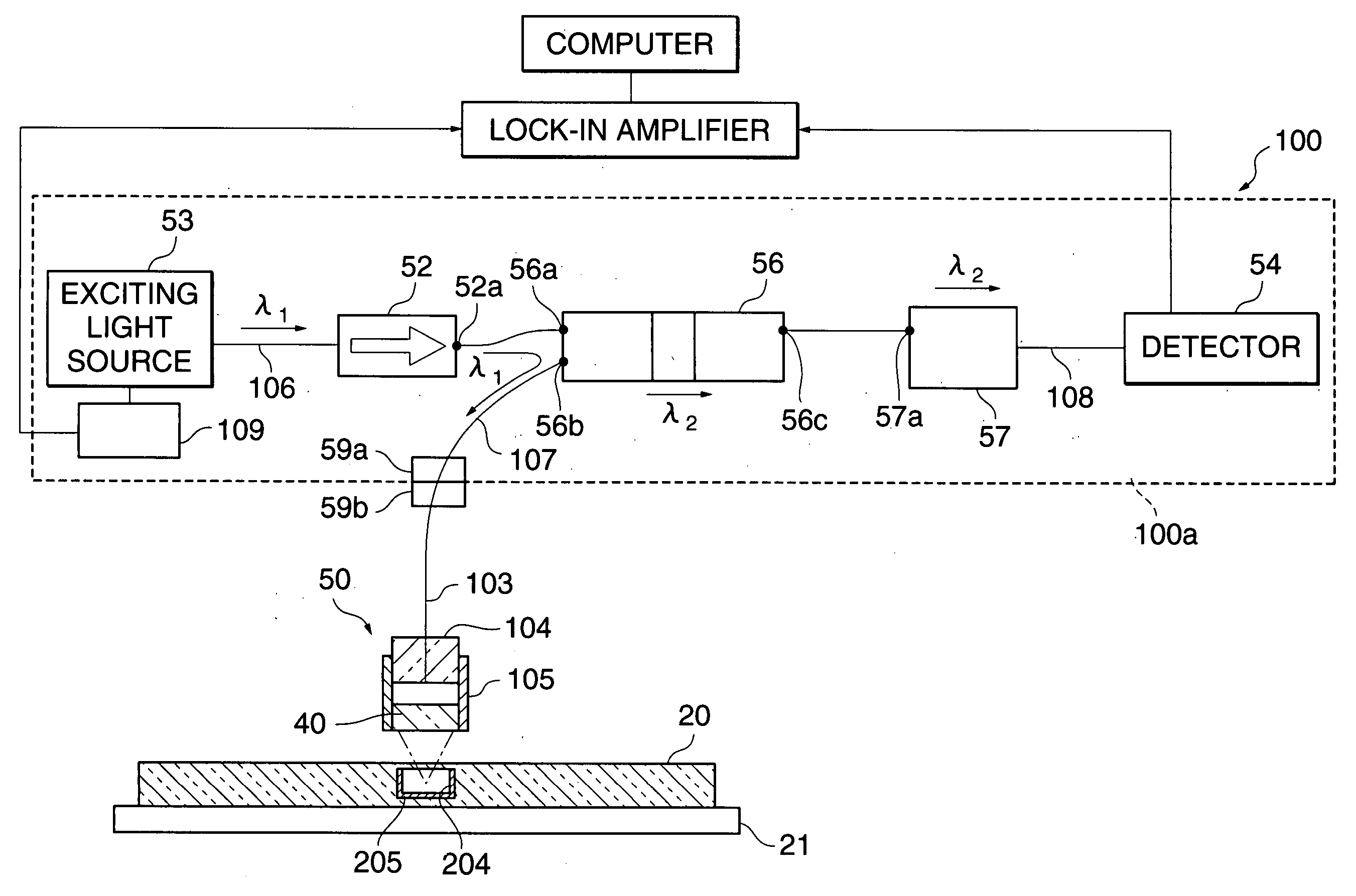
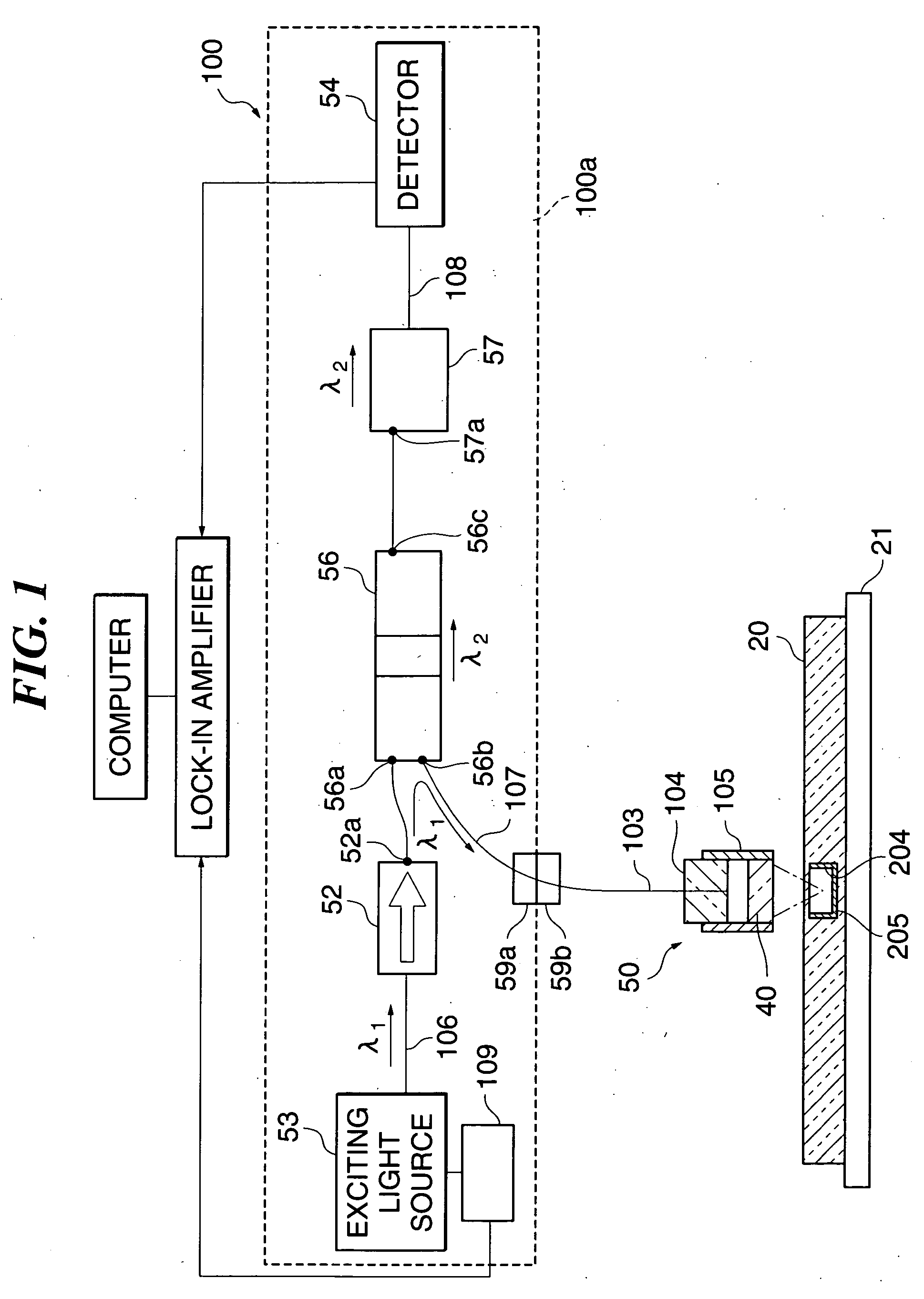
[0084]FIG. 1 is a view schematically showing the construction of a microchemical system, which is a fluorescence analyzer according to an embodiment of the present invention.

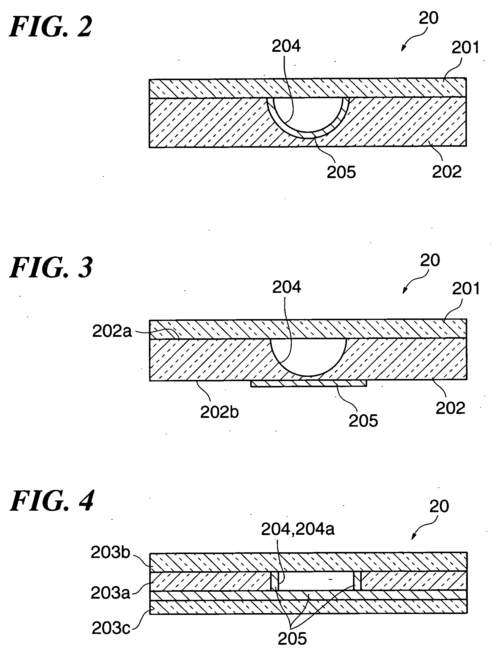
[0085] As shown in FIG. 1, the microchemical system 100 is comprised of a fluorescence analysis optical module 100a, a lens-possessing optical fiber (hereinafter referred to as a “probe”) 50 that condenses exciting light onto a sample solution in a channel 204 inside a fluorescence analysis chip 20, and a sample stage 21 on which the fluorescence analysis chip 20 is mounted.

[0086] The sample stage 21 has a moving mechanism, not shown, that positions the sample by moving the sample stage 21 relative to the probe 50. Although the sample stage 21 has such a moving mechanism in the present embodiment, so long as positioning of the sample can be carried out, there is no limitation to this, but rather the prob...


PUM

PropertyMeasurementUnit
angle of incidenceaaaaaaaaaa
dominant wavelength λ3aaaaaaaaaa

Abstract

A fluorescence analysis optical multiplexer / demultiplexer, a fluorescence analysis optical module, a fluorescence analyzer, a fluorescence / photothermal conversion spectroscopic analyzer, and a fluorescence analysis chip, according to which LIF analysis can be carried out easily and with high sensitivity, and moreover photothermal conversion spectroscopic analysis can be carried out easily and simultaneously with the LIF analysis. A microchemical system 100 as the fluorescence analyzer is comprised of a fluorescence analysis optical module 100a, a probe 50 that condenses exciting light onto a sample solution in a channel 204 inside a fluorescence analysis chip 20, and a sample stage 21 on which the fluorescence analysis chip 20 is mounted. The fluorescence analysis optical module 100a is comprised of an exciting light source 53 that outputs exciting light of dominant wavelength λ1, a fluorescence analysis optical multiplexer / demultiplexer 56 for use in the fluorescence analyzer which analyzes fluorescence of dominant wavelength λ2 (λ2>λ1) emitted from the sample upon the sample being irradiated with the exciting light via the probe 50, a detector 54 that receives the fluorescence, an optical fiber 106 that connects the fluorescence analysis optical multiplexer / demultiplexer 56 to the exciting light source 53, an optical fiber 107 that connects the fluorescence analysis optical multiplexer / demultiplexer 56 to the probe 50, and an optical fiber 108 that connects the fluorescence analysis optical multiplexer / demultiplexer 56 to the detector 54. The channel 204 through which the sample solution is passed is coated with a reflective metal film 205.

Description

[0001] This application is a U.S. Continuation Application of International Application PCT / JP2004 / 009582 filed 30 Jun. 2004.TECHNICAL FIELD [0002] The present invention relates to a fluorescence analysis optical multiplexer / demultiplexer, a fluorescence analysis optical module, a fluorescence analyzer, a fluorescence / photothermal conversion spectroscopic analyzer, and a fluorescence analysis chip, and more particularly to a fluorescence analysis optical multiplexer / demultiplexer, a fluorescence analysis optical module, a fluorescence analyzer, a fluorescence / photothermal conversion spectroscopic analyzer, and a fluorescence analysis chip which carry out laser induced fluorescence analysis and photothermal conversion spectroscopic analysis. BACKGROUND ART [0003] Microchemical systems are systems for carrying out highly sensitive detection or analysis on a very small amount of a sample using a capillary tube or a fluorescence analysis chip. For example, a fluorescence analysis chip h...

Claims


Application Information

Patent Timeline
Patent Type & Authority Applications(United States)
IPC IPC(8): G01N21/64G01N25/16
CPCG01N21/645G01N2021/6482G01N2021/6484
Inventor FUKUZAWA, TAKASHIYAMAGUCHI, JUNHATTORI, AKIHIKOMIWA, TAKAO
Owner NIPPON SHEET GLASS CO LTD
Why Eureka
Try Eureka