
Method for Charging Nonaqueous Electrolytic Secondary Cell and Nonaqueous Electrolytic Secondary Cell

a nonaqueous electrolyte and secondary cell technology, applied in the direction of secondary cell servicing/maintenance, cell components, electrochemical generators, etc., can solve the problems of insufficient life performance of manganese-based nonaqueous electrolyte secondary battery and inability to obtain sufficient life performance, etc., to achieve the effect of improving life performan

Inactive Publication Date: 2006-06-08
GS YUASA CORP
View PDF4 Cites 7 Cited by
  • Summary
  • Abstract
  • Description
  • Claims
  • Application Information

AI Technical Summary

Benefits of technology

[0011] It is to be noted that when using the nonaqueous electrolyte secondary battery to which several cycles of discharging / charging are applied, the battery is charged after discharging up to the discharge end voltage of 2.75 V at 0.05 CA primarily in order to eliminate the influence of residual electricity quantity.
[0033] Also, as a separator of the nonaqueous electrolyte secondary battery according to the present invention, woven fabric, nonwoven fabric, fine porous synthetic resin membrane or the like can be used, and synthetic resin fine porous membranes can particularly preferably be used. Of these, fine porous polyolefin membranes such as fine porous polyethylene membrane, fine porous polypropylene membrane and fine porous membrane combination of these are preferably used because of their thickness, membrane strength, membrane resistance and the like.

Problems solved by technology

However, there is a problem in that a conventional manganese-based nonaqueous electrolyte secondary battery has an insufficient life performance.
However, sufficient life performance cannot be obtained even by using this technology, and further improvement of life performance has been anticipated.

Method used


Image

  • Method for Charging Nonaqueous Electrolytic Secondary Cell and Nonaqueous Electrolytic Secondary Cell
  • Method for Charging Nonaqueous Electrolytic Secondary Cell and Nonaqueous Electrolytic Secondary Cell
  • Method for Charging Nonaqueous Electrolytic Secondary Cell and Nonaqueous Electrolytic Secondary Cell

Examples


Embodiment Construction

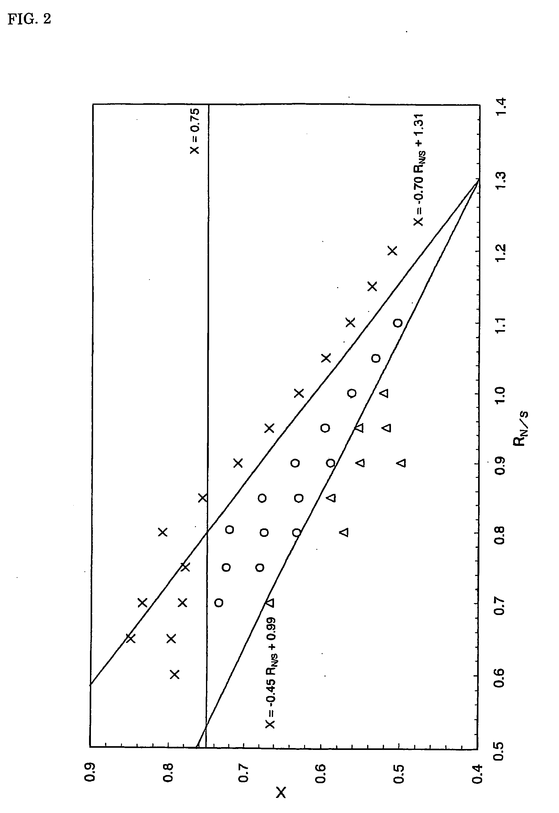
[0037] Next, the effects of the present invention will be described specifically by way of examples, but the present invention is not limited to the examples.

[0038]

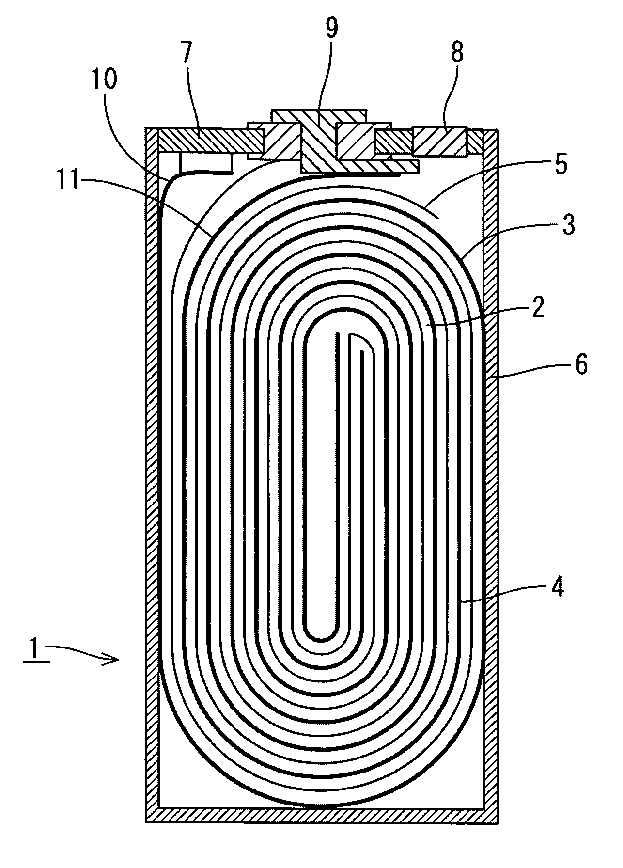
[0039]FIG. 1 is a schematic sectional view of a prismatic nonaqueous electrolyte secondary battery used in the following examples and comparative examples. The nonaqueous electrolyte secondary battery 1 is configured by housing a flat wound electrode group 2 in which a positive electrode plate 3 composed by applying positive electrode mixture to a positive electrode current collector composed of aluminum foil and a negative electrode plate 4 composed by applying negative electrode mixture to a negative electrode current collector composed of copper foil are wound through a separator 5, and nonaqueous electrolyte in a battery case 6.

[0040] A battery lid 7 having a safety valve 8 is fixed to the battery case 6 by laser welding; a negative electrode terminal 9 is connected to the negative electrode plate 4 through a negati...


PUM

PropertyMeasurementUnit
voltageaaaaaaaaaa
mole ratioaaaaaaaaaa

Abstract

A charging method of a nonaqueous electrolyte secondary battery which comprises a positive electrode plate including a lithium-manganese composite oxide with spinel structure; a negative electrode plate including graphite capable of storing and discharging lithium; and nonaqueous electrolyte. When the ratio of a theoretical capacity of the negative electrode plate to a theoretical capacity of the positive electrode plate is set as RN / s and the graphite which has stored lithium by charging is represented by LixC6, the nonaqueous electrolyte secondary battery is characteristically charged so that the maximum value Xmax X can have satisfies the following Conditions (1) and (2): Xmax≦0.75  Condition (1) Xmax≦−0.70RN / S+1.31  Condition (2) The life performance is remarkably improved by charging the nonaqueous electrolyte secondary battery while satisfying the Conditions.

Description

TECHNICAL FIELD [0001] The present invention relates to a nonaqueous electrolyte secondary battery and a charging method thereof. BACKGROUND ART [0002] The nonaqueous electrolyte secondary battery which has a lithium transition metal composite oxide such as lithium cobalt oxide, lithium nickelate, or lithium manganese spinel as a positive active material and a carbon material capable of storing and discharging lithium as a negative active material, is known for its excellent characteristics such as high energy density and high power. Particularly, a manganese-based nonaqueous electrolyte secondary battery which uses a lithium-manganese composite oxide with spinel structure as a positive active material is employed as a high-power power source for an electric vehicle and a hybrid electric vehicle owing to its good discharge characteristics and excellent safety, and demand for the battery is expected to further expand. [0003] However, there is a problem in that a conventional manganes...

Claims


Application Information

Patent Timeline
Patent Type & Authority Applications(United States)
IPC IPC(8): H01M10/44H01M4/50H01M4/58H01M4/131H01M4/485H01M4/505H01M4/525H01M4/587H01M10/05H01M10/052H01M10/0525H01M10/056H01M10/42
CPCH01M4/131H01M4/485H01M4/505H01M4/525H01M4/587H01M10/052H01M10/0525H01M10/056H01M10/44H01M2004/021H01M2010/4292Y02E60/122Y02E60/10
Inventor SEYAMA, YUKITAKA
Owner GS YUASA CORP
Learn More