Manufacturing method and current collector

a current collector and manufacturing method technology, applied in the field of current collector manufacturing, can solve the problems of sintering and densification of current collectors, and achieve the effects of increasing mechanical integrity and adhesion, reducing manufacturing costs, and reducing labor intensity

Inactive Publication Date: 2006-06-15
PRAXAIR TECH INC
View PDF13 Cites 37 Cited by
  • Summary
  • Abstract
  • Description
  • Claims
  • Application Information

AI Technical Summary

Benefits of technology

[0008] After deposition of the slurry and subsequent removal of any binder, solvent, plasticizer or dispersant, the particles that comprise the current collector are loosely bound together and poorly adhered to the electrode. The layer has little, if any, mechanical integrity and is easily removed. In order to consolidate this layer, that is, to increase the mechanical integrity and adherence, it is normal practice to subject the layer to an additional heat treatment at a temperature higher than the temperature at which the device is designed to be used, typically, about 700° C. The problem is that this additional heat-treatment generally results in sintering and densification of the current collector. Densification implies the elimination of porosity in that layer and open porosity is a fundamental requirement for high performance device operation. This is especially a problem when forming silver current collectors as silver sinters and densities very readily.

Problems solved by technology

In order to consolidate this layer, that is, to increase the mechanical integrity and adherence, it is normal practice to subject the layer to an additional heat treatment at a temperature higher than the temperature at which the device is designed to be used, typically, about 700° C. The problem is that this additional heat-treatment generally results in sintering and densification of the current collector.
This is especially a problem when forming silver current collectors as silver sinters and densities very readily.

Method used


Image

  • Manufacturing method and current collector
  • Manufacturing method and current collector
  • Manufacturing method and current collector

Examples


Embodiment Construction

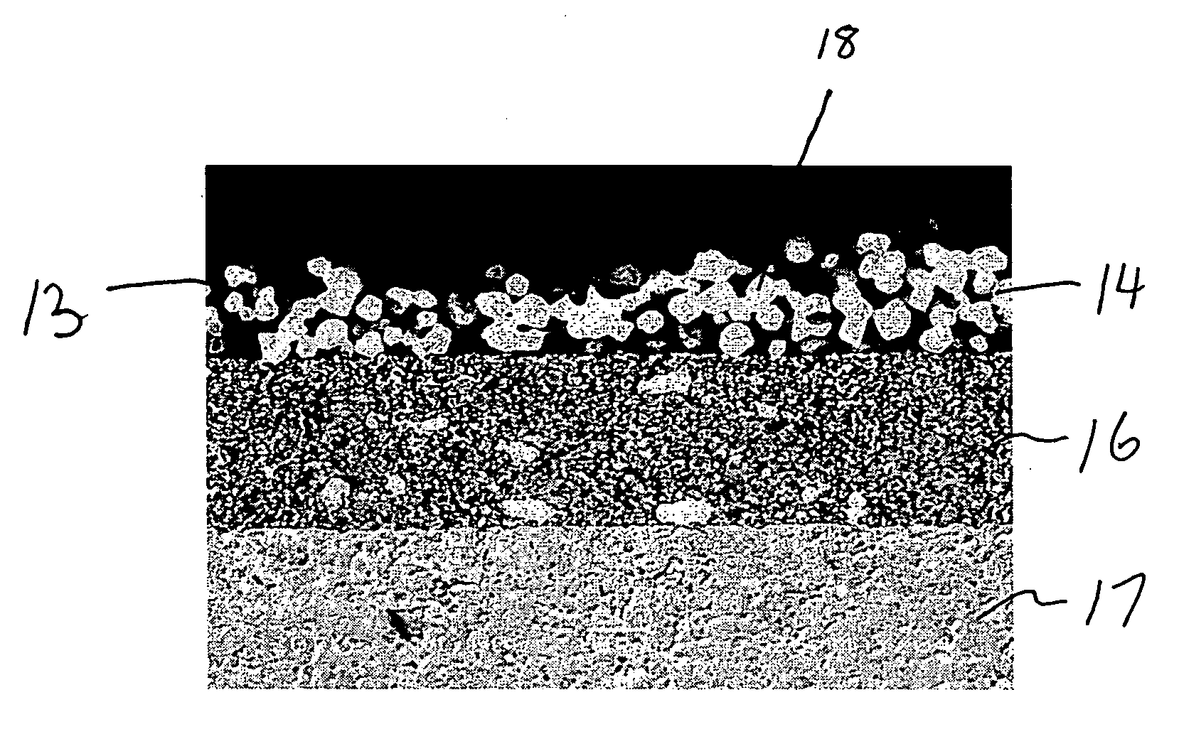
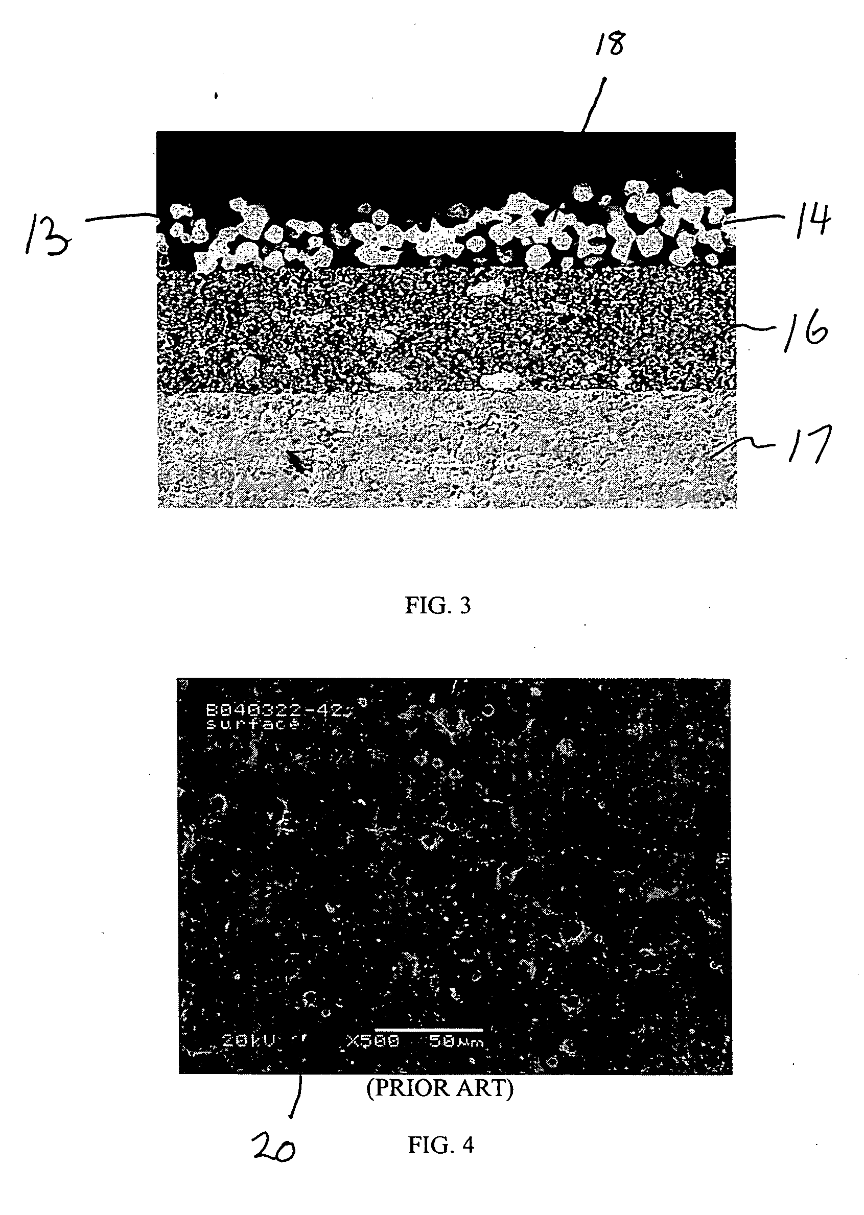
[0023] In accordance with a method of the present invention, a porous current collector is formed from a powder containing a metal or metal alloy having surface deposits of a metallic oxide. Such a powder can be produced by methods well known in the art, for example by wash-coating or mechanical alloying. For exemplary purposes, a silver powder, designated as FERRO S11000-02 powder, was obtained from Ferro Corporation, Electronic Material Systems, 3900 South Clinton Avenue, South Plainfield, N.J. 07080 USA. The size of particles contained in such powder is between about 3 and about 10 microns in diameter and the particles have a low specific surface are of about 0.2 m2 / gram. These features are preferred in that it is believed that they limit the driving force for sintering and densification. Zirconia surface deposits were formed on such powder such that the zirconia accounted for about 0.25 percent of the weight of the coated particle.

[0024] As may be appreciated, other electrical ...


PUM

PropertyMeasurementUnit
particle sizeaaaaaaaaaa
pore sizeaaaaaaaaaa

Abstract

A method of forming a current collector layer on electrode layers of an electrochemical air separation element and a current collector. A slurry is prepared that contains electrically conductive particles having surface deposits of a metallic oxide on a metal or metal alloy conductor. The metallic oxide surface deposit constitutes a lower weight percentage of the electrically conductive particles than the metal or metal alloy. The slurry is applied to a structure that contains an electrolyte and electrode layers. The slurry can be applied by dip coating techniques. The resultant coated form is then fired to partly sinter the electrically conductive particles and thereby to obtain porous current collector layers affixed to the electrode layers. The current collector of the present invention is between about 5 microns and about 100 microns thick and preferably has a porosity of between about 10 percent and about 70 percent with pores having a pore size of between about 0.1 microns and about 20 microns.

Description

FIELD OF THE INVENTION [0001] The present invention relates to a method of manufacturing a current collector and the current collector itself in which the current collector is formed as a porous layer in contact with an electrode of an electrochemical air separation device to conduct an electrical current. More particularly, the present invention relates to such a method and current collector in which the current collector is formed of electrically conductive particles having a surface deposit of a metallic oxide. BACKGROUND OF THE INVENTION [0002] Electrochemical devices for separating oxygen from air all utilize one or more electrochemical air separation elements formed of an electrolyte layer sandwiched between one or more electrode layers. Such devices include oxygen concentrators, hydrolyzers and fuel cells. [0003] The electrolyte is capable of conducting oxygen ions at elevated temperatures. Typical materials used in forming the electrolyte include yttria stabilized zirconia a...

Claims


Application Information

Patent Timeline
Patent Type & Authority Applications(United States)
IPC IPC(8): H01M2/28H01M10/00H01M50/541
CPCB22F3/11B22F7/002B22F2998/00C22C32/001H01M4/8621H01M4/8889H01M8/0232H01M8/0236H01M8/0245H01M8/1206H01M2008/1293B22F1/02Y02E60/50Y02E60/525H01M8/1231Y02P70/50B22F1/16H01M10/00H01M50/541
Inventor CHRISTIE, GERVASE MAXWELLLANE, JONATHAN ANDREW
Owner PRAXAIR TECH INC
Why Eureka
Try Eureka