[0027] These and other advantages, aspects and novel features of the present invention, as well as details of an illustrated embodiment thereof, will be more fully understood from the following description and drawings.
[0028]FIG. 1a is a block diagram of an exemplary system for providing integrated services between a cellular network and a digital
video broadcast network, in accordance with an embodiment of the invention.
[0032]FIG. 1e is a high-level block diagram of exemplary DVB-H
receiver circuitry in a mobile terminal, which may be utilized in connection with an embodiment of the invention.
[0033]FIG. 1f is a block diagram illustrating the sharing of a
multiplexer (MUX) by a plurality of MPEG2 services, which may be utilized in connection with an embodiment of the invention.
[0034]FIG. 2a is a block diagram of a mobile terminal that is adapted to receive VHF / UHF broadcasts and cellular communications, in accordance with an embodiment of the invention.
[0035]FIG. 2b is a block diagram illustrating receive
processing circuit of an RF
integrated circuit (RFIC), in accordance with an embodiment of the invention.
[0036]FIG. 3 is a high-level block diagram illustrating an exemplary configuration for a RFIC and a base band
processing circuit, in accordance with an embodiment of the invention.
[0037]FIG. 4a is a block diagram of an exemplary mobile
receiver single antenna architecture for handling world band cellular and broadcast services, in accordance with an embodiment of the invention.
[0038]FIG. 4b is a block diagram of an exemplary mobile
receiver dual antenna architecture for handling world band cellular and broadcast services, in accordance with an embodiment of the invention.
[0041]FIG. 4e is a block diagram of an exemplary mobile receiver
multiple antenna architecture for handling world band cellular and broadcast services, in accordance with an embodiment of the invention.
[0040]FIG. 4d is a block diagram of an exemplary mobile receiver
multiple antenna architecture for handling world band cellular and broadcast services, in accordance with an embodiment of the invention.
[0041]FIG. 4e is a block diagram of an exemplary mobile receiver
multiple antenna architecture for handling world band cellular and broadcast services, in accordance with an embodiment of the invention.
[0042]FIG. 4f is a block diagram of an exemplary mobile receiver multiple antenna architecture for handling world band cellular and broadcast services, in accordance with an embodiment of the invention.
[0043]FIG. 4g is a block diagram of an exemplary mobile receiver multiple antenna architecture for handling world band cellular and broadcast services, in accordance with an embodiment of the invention.
[0044]FIG. 4h is a block diagram of an exemplary mobile receiver multiple antenna architecture for handling world band cellular and broadcast services, in accordance with an embodiment of the invention.
[0018] A method for an antenna architecture that handles World band cellular and
broadcast channels may be provided. The method may comprise receiving at a first
radio frequency integrated circuit (RFIC) integrated within a mobile terminal, first signals via a first antenna, where the first signals comprise signals within at least one of a 2100 MHz band and a 1900 MHz band. The method may further comprise receiving at a second RFIC integrated within the mobile terminal, second signals via the first antenna, where the second signals comprise signals within at least one of a 1900 MHz band, a 1800 MHz band, a 900 MHz band and a 850 MHz band. Additionally, third signals may be received via the first antenna at a third RFIC integrated within the mobile terminal, where the third signals comprise signals within a VHF / UHF
broadcast band.
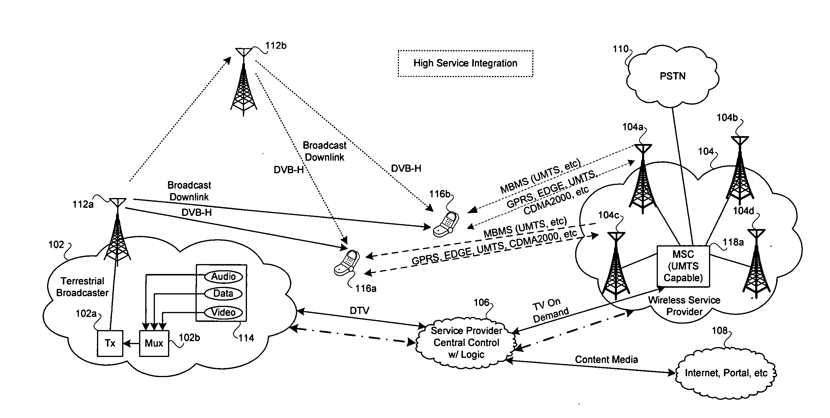
[0046]FIG. 1a is a block diagram of an exemplary system for providing integrated services between a cellular network and a digital
video broadcast network, in accordance with an embodiment of the invention. Referring to FIG. 1a, there is shown terrestrial broadcaster network 102,
wireless service provider network 104,
service provider 106, portal 108, public switched
telephone network 110, and mobile terminals (MTs) 116a and 116b. The terrestrial broadcaster network 102 may comprise
transmitter (Tx) 102a,
multiplexer (Mux) 102b, and information content source 114. The content source 114 may also be referred to as a data carousel, which may comprise audio, data and video content. The terrestrial broadcaster network 102 may also comprise VHF / UHF broadcast antennas 112a and 112b. The
wireless service provider network 104 may comprise mobile switching center (MSC) 118a, and a plurality of cellular base stations 104a, 104b, 104c, and 104d.
[0047] The terrestrial broadcaster network 102 may comprise suitable equipment that may be adapted to
encode and / or encrypt data for transmission via the
transmitter 102a. The
transmitter 102a in the terrestrial broadcast network 102 may be adapted to utilize VHF / UHF
broadcast channels to communicate information to the mobile terminals 116a, 116b. The
multiplexer 102b associated with the terrestrial broadcaster network 102 may be utilized to
multiplex data from a plurality of sources. For example, the multiplexer 102b may be adapted to
multiplex various types of information such as audio, video and / or data into a single
pipe for transmission by the transmitter 102a. Content media from the portal 108, which may be handled by the service provider 106 may also be multiplexed by the multiplexer 102b. The portal 108 may be an ISP service provider.
[0048] In one aspect of the invention, the terrestrial broadcaster network 102 may be adapted to provide one or more
digital television (DTV) channels to the service provider 106. In this regard, the terrestrial broadcaster network 102 may comprise suitable high-speed or
broadband interfaces that may be utilized to facilitate transfer of the DTV channels from the terrestrial broadcast network 102 to the service provider. The service provider 106 may then utilize at least a portion of the DTV channels to provide television (TV)
on demand service, or other similar types of services to the
wireless service provider network 104. Accordingly, the service provider 106 may further comprise suitable high-speed or
broadband interfaces that may be utilized to facilitate the transfer of related TV
on demand information to the MSC 118a.
[0049] Although communication links between the terrestrial broadcast network 102 and the service provider 106, and also the communication links between the service provider 106 and the wireless service provider 104 may be
wired communication links, the invention may be not so limited. Accordingly, at least one of these communication links may be wireless communication links. In an exemplary embodiment of the invention, at least one of these communication links may be an 802.x based
communication link such as 802.16 or
WiMax broadband access
communication link. In another exemplary embodiment of the invention, at least one of these connections may be a broadband
line of sight (LOS) connection.
[0050] The wireless service provider network 104 may be a cellular or personal communication service (PCS) provider that may be adapted to
handle broadcast UMTS (B-UMTS). The term cellular as utilized herein refers to both cellular and PCS frequencies bands. Hence, usage of the term cellular may comprise any band of frequencies that may be utilized for
cellular communication and / or any band of frequencies that may be utilized for PCS communication. Notwithstanding, broadcast UMTS (B-UMTS) may also be referred to as MBMS. MBMS is a high-speed data service that is overlaid on WCDMA to provide much higher data rates than may be provided by core WCDMA. In this regard, the B-UMTS services may be superimposed on the cellular or PCS network.
[0051] The wireless service provider network 104 may utilize cellular or PCS access technologies such as
GSM, CDMA, CDMA2000, WCDMA, AMPS, N-AMPS, and / or TDMA. The cellular network may be utilized to offer bi-directional services via uplink and downlink communication channels, while the B-UMTS or MBMS network may be utilized to provide a unidirectional broadband services via a downlink channel. The B-UMTS or MBMS unidirectional downlink channel may be utilized to broadcast content media and / or
multimedia type information to the mobile terminals 116a and 116b. Although MBMS provides only unidirectional downlink communication, the invention may be not so limited. In this regard, other
bidirectional communication methodologies comprising uplink and downlink capabilities, whether symmetric or asymmetric, may be utilized.
[0052] Although the wireless service provider network 104 is illustrated as a
GSM, CDMA, WCDMA based network and / or variants thereof, the invention is not limited in this regard. Accordingly, the wireless service provider network 104 may be an 802.11 based
wireless network or wireless
local area network (WLAN). The wireless service provider network 104 may also be adapted to provide 802.11 based wireless communication in addition to
GSM, CDMA, WCDMA, CDMA2000 based network and / or variants thereof. In this case, the mobile terminals 116a, 116b may also be compliant with the 802.11 based
wireless network.
[0053] In accordance with an exemplary embodiment of the invention, if the mobile terminal (MT) 116a is within an operating range of the VHF / UHF
broadcasting antenna 112a and moves out of the latter's operating range and into an operating range of the VHF / UHF
broadcasting antenna 112b, then VHF / UHF broadcasting antenna 112b may be adapted to provide VHF / UHF broadcast services to the mobile terminal 116a. If the mobile terminal 116a subsequently moves back into the operating range of the VHF / UHF broadcasting antenna 112a, then the broadcasting antenna 112a may be adapted to provide VHF / UHF broadcasting service to the mobile terminal 116a. In a somewhat similar manner, if the mobile terminal (MT) 116b is within an operating range of the VHF / UHF broadcasting antenna 112b and moves out of the latter's operating range and into an operating range of the broadcasting antenna 112a, then the VHF / UHF broadcasting antenna 112a may be adapted to provide VHF / UHF broadcasting service to the mobile terminal 116b. If the mobile terminal 116b subsequently moves back into the operating range of broadcasting antenna 112b, then the VHF / UHF broadcasting antenna 112b may be adapted to provide VHF / UHF broadcast services to the mobile terminal 116b.
[0054] The service provider 106 may comprise suitable interfaces, circuitry, logic and / or code that may be adapted to facilitate communication between the terrestrial broadcasting network 102 and the wireless communication network 104. In an illustrative embodiment of the invention the service provider 106 may be adapted to utilize its interfaces to facilitate exchange control information with the terrestrial broadcast network 102 and to exchange control information with the wireless service provider 104. The control information exchanged by the service provider 106 with the terrestrial broadcasting network 102 and the wireless communication network 104 may be utilized to control certain operations of the mobile terminals, the terrestrial broadcast network 102 and the wireless communication network 104.
[0055] In accordance with an embodiment of the invention, the service provider 106 may also comprise suitable interfaces, circuitry, logic and / or code that may be adapted to
handle network policy decisions. For example, the service provider 106 may be adapted to manage a load on the terrestrial broadcast network 102 and / or a load on the wireless service provider network 104.
Load management may be utilized to distribute the flow of information throughout the terrestrial broadcast network 102 and / or a load on the wireless service provider network 104. For example, if information is to be broadcasted via the wireless service provider network 104 to a plurality of mobile terminals within a particular
cell handled by the
base station 104a and it is determined that this may overload the wireless service provider network 104, then the terrestrial broadcast network 102 may be configured to broadcast the information to the mobile terminals.
[0056] The service provider 106 may also be adapted to
handle certain types of service requests, which may have originated from a mobile terminal. For example, the mobile terminal 116a may request that information be delivered to it via a downlink VHF / UHF broadcast channel. However, a downlink VHF / UHF broadcast channel may be unavailable for the delivery of the requested information. As a result, the service provider 106 may
route the requested information through an MBMS channel via the
base station 104c to the mobile terminal 116a. The requested information may be acquired from the content source 114 and / or the portal 108. In another example, the mobile terminal 116b may request that information be delivered to it via a downlink cellular channel. However, the service provider 106 may determine that delivery of the information is not critical and / or the cheapest way to deliver to the mobile terminal 116b is via a downlink VHF / UHF broadcast channel. As a result, the service provider 106 may
route the requested information from the portal 108 or content service 114 to the mobile terminal 116b. The service provider 106 may also have the capability to send at least a portion of information to be delivered to, for example, mobile terminal 116a via the VHF / UHF broadcast channel and a remaining portion of the information to be delivered via the cellular broadcast channel.
[0057] The portal 108 may comprise suitable logic, circuitry and / or code that may be adapted to provide content media to the service provider 106 via one or more communication links. These communication links, although not shown, may comprise wired and / or wireless communication links. The content media that may be provided by the portal 108 may comprise audio, data, video or any combination thereof. In this regard, the portal 108 may be adapted to provide one or more specialized information services to the service provider 106.
[0058] The public switched
telephone network (PSTN) 110 may be coupled to the MSC 118a. Accordingly, the MSC 118a may be adapted to switch calls originating from within the PSTN 110 to one or more mobile terminals serviced by the wireless service provider 104. Similarly, the MSC 118a may be adapted to switch calls originating from mobile terminals serviced by the wireless service provider 104 to one or more telephones serviced by the PSTN 110.
[0059] The information content source 114 may comprise a data carousel. In this regard, the information content source 114 may be adapted to provide various information services, which may comprise online data including audio, video and
data content. The information content source 114 may also comprise file download, and
software download capabilities. In instances where a mobile terminal fails to acquire requested information from the information content source 114 or the requested information is unavailable, then the mobile terminal may acquire the requested information via, for example, a B-UMTS from the portal 108. The request may be initiated through an uplink
cellular communication path.
[0060] The mobile terminals (MTs) 116a and 116b may comprise suitable logic, circuitry and / or code that may be adapted to handle the
processing of uplink and downlink cellular channels for various access technologies and broadcast VHF / UHF technologies. In an exemplary embodiment of the invention, the mobile terminals 116a, 116b may be adapted to utilize one or more cellular access technologies such as GSM, GPRS, EDGE, CDMA, WCDMA, CDMA2000, HSDPA and MBMS (B-UMTS). The mobile terminal may also be adapted to receive and process VHF / UHF broadcast signals in the VHF / UHF bands. For example, a mobile terminal may be adapted to receive and process DVB-H signals. A mobile terminal may be adapted to request information via a first cellular service and in response, receive corresponding information via a VHF / UHF
broadcast service. A mobile terminal may also be adapted to request information from a service provider via a cellular service and in response, receive corresponding information via a data service, which is provided via the cellular service. The mobile terminals may also be adapted to receive VHF / UHF broadcast information from either the base stations 104a, 104b, 104c, 104d or the VHF / UHF broadcast antennas 112a and 112b. In instances where a mobile terminal receives broadcast information from any of the base stations 104a, 104b, 104c, or 104d via a downlink MBMS
communication channel, then the mobile terminal may communicate corresponding uplink information via an uplink
cellular communication channel.
[0061] In one embodiment of the invention, a mobile terminal may be adapted to utilize a plurality of broadcast integrated circuits for receiving and processing VHF / UHF channels, and a plurality of cellular integrated circuits for receiving and processing cellular or PCS channels. In this regard, the plurality of cellular integrated circuits may be adapted to handle different cellular access technologies. For example, at least one of the cellular integrated circuits may be adapted to handle GSM, and at least one of the cellular integrated circuits may be adapted to handle WCDMA. For broadcast channels, each of the plurality of broadcast integrated circuits may be adapted to handle at least one VH / UHF channel.
[0062] In another embodiment of the invention, a mobile terminal may be adapted to utilize a single broadcast integrated circuit for receiving and processing VHF / UHF channels, and a single cellular integrated circuit for receiving and processing cellular or PCS channels. In this regard, the single cellular integrated circuit may be adapted to handle different cellular access technologies. For example, at least one of the cellular integrated circuit may be adapted to handle GSM, and at least one of the cellular integrated circuits may be adapted to handle WCDMA. For broadcast channels, the single broadcast integrated circuit may be adapted to handle at least one VHF / UHF channel. Each of the mobile terminals may comprise a single
memory interface that may be adapted to handle processing of the broadcast communication information and processing of cellular communication information. In this regard, an uplink cellular communication path may be utilized to facilitate receiving of broadcast information via a broadcast communication path.
[0063] In another embodiment of the invention, a mobile terminal may be adapted to utilize a single integrated circuit for receiving and processing broadcast VHF / UHF channels, and for receiving and processing cellular or PCS channels. In this regard, the single broadcast and cellular integrated circuit may be adapted to handle different cellular access technologies. For example, the single integrated circuit may comprise a plurality of modules each of which may be adapted to receive and process a particular cellular
access technology or a VHF / UHF broadcast channel. Accordingly, a first module may be adapted to handle GSM, a second module may be adapted to handle WCDMA, and a third module may be adapted to handle at least one VHF / UHF channel.
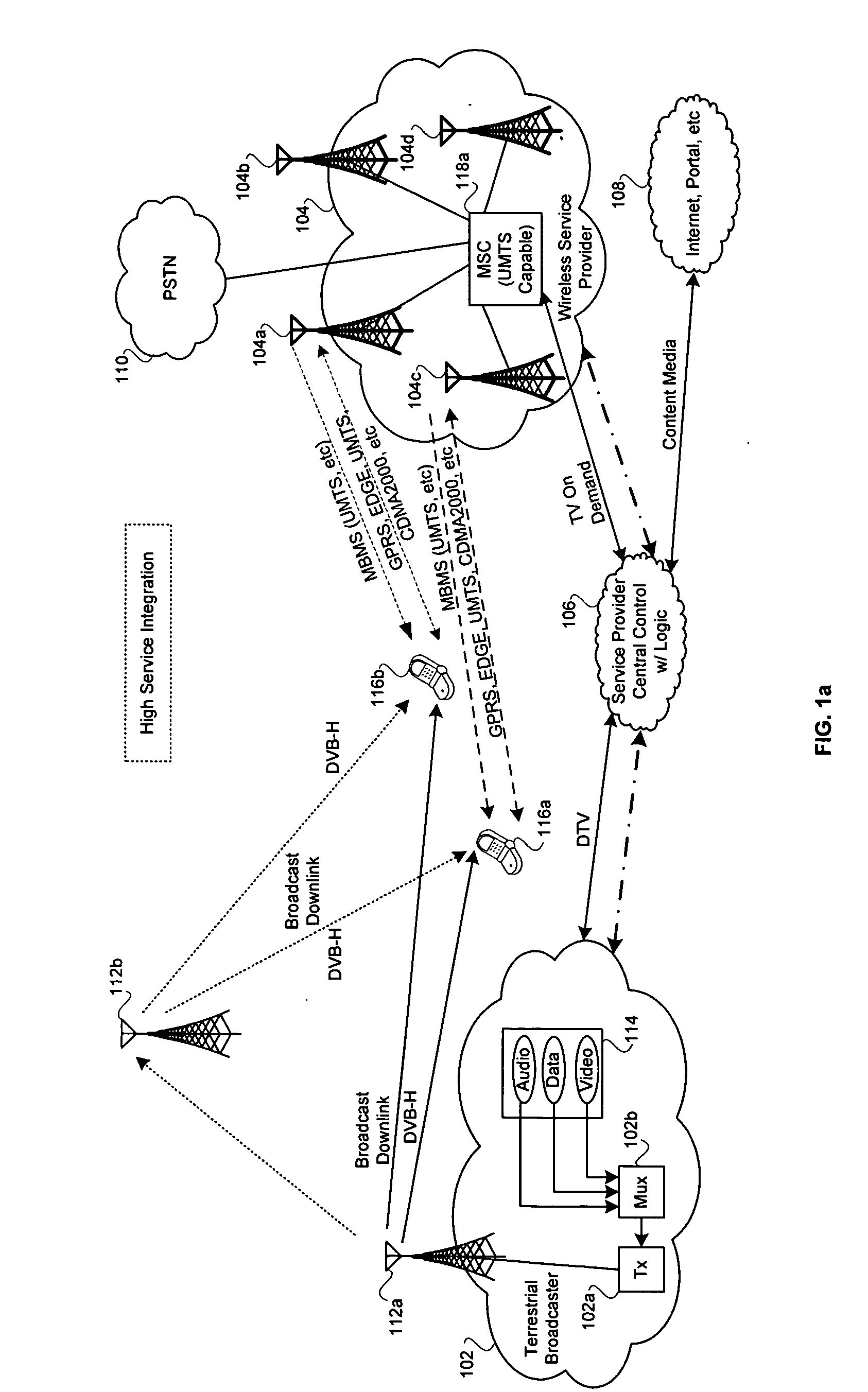
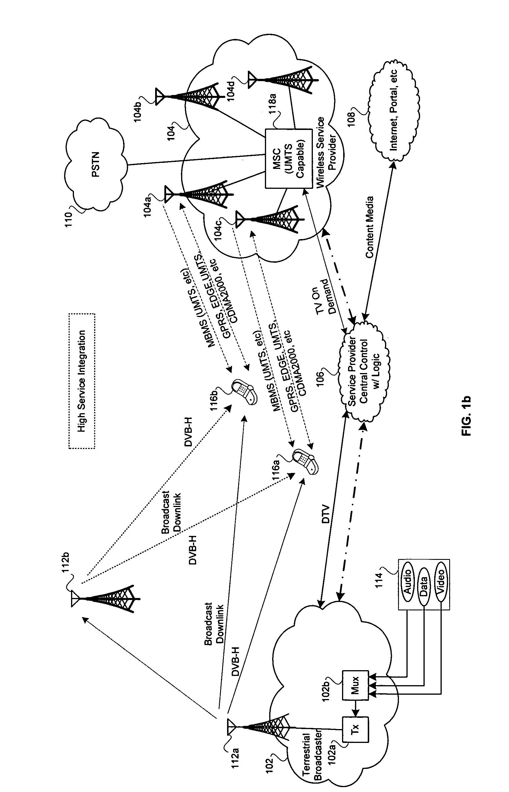
[0064]FIG. 1b is a block diagram of an alternative embodiment of the exemplary system of FIG. 1a for providing integrated services between a cellular network and a digital
video broadcast network, in accordance with an embodiment of the invention. Referring to FIG. 1b, there is shown terrestrial broadcaster network 102, wireless service provider network 104, service provider 106, portal 108, public switched
telephone network 110, and mobile terminals (MTs) 116a and 116b. The terrestrial broadcaster network 102 may comprise transmitter (Tx) 102a, multiplexer (Mux) 102b, and VHF / UHF broadcast antennas 112a and 112b. Although VHF / UHF broadcast antenna 112b is illustrated separately from the terrestrial broadcast network 102, it may still be part of the terrestrial broadcast network 102. The wireless service provider network 104 may comprise mobile switching center (MSC) 118a, and a plurality of cellular base stations 104a, 104b, 104c, and 104d.
[0065] The system of FIG. 1b is somewhat similar to the FIG. 1a with the exception that FIG. 1b has the content source 114 located external to the terrestrial broadcast network 102. The content source 114, which may also be referred to as a data carousel, may comprise audio, data and video content. At least a portion of the audio, data and / or video content stored in the content source 114 may be linked so that if information cannot be retrieved from the content source 114, then it may be received from the portal 108. In the system of FIG. 1b, a provider other than the terrestrial broadcaster 102 may manage the content source 114. Notwithstanding, the audio, video and / or data from the content source 114 may still be multiplexed by the multiplexer 102b in the terrestrial broadcast network 114.
[0066]FIG. 1c is a block diagram of an alternative embodiment of the exemplary system of FIG. 1a for providing integrated services between a cellular network and a digital video broadcast network, in accordance with an embodiment of the invention. Referring to FIG. 1c, there is shown terrestrial broadcaster network 102, wireless service provider network 104, portal 108, public switched telephone network 110, and mobile terminals (MTs) 116a and 116b. The terrestrial broadcaster network 102 may comprise transmitter (Tx) 102a, multiplexer (Mux) 102b, service provider 106, and VHF / UHF broadcast antennas 112a and 112b. The wireless service provider network 104 may comprise mobile switching center (MSC) 118a, and a plurality of cellular base stations 104a, 104b, 104c, and 104d.
[0067] The system of FIG. 1c is somewhat similar to the FIG. 1a with the exception that FIG. 1b has the service provider 106 co-located with the terrestrial broadcast network 102. In this regard, the terrestrial broadcast network 102 may control the functions of the service provider 106. Since the terrestrial broadcast network 102 controls the functions of the service provider, the broadcast services may be more efficiently provided to the mobile terminals via the MBMS path provided by the wireless service provider 104 and / or the VHF / UHF broadcast downlink path provided by the terrestrial broadcaster network 102. Hence, instead of having to send information to an externally located service provider, the integrated control and logic services provided the terrestrial broadcaster network 102 and service provider 106 may instantly make decisions of how best to handle information for a mobile terminal.
[0068]FIG. 1d is a block diagram of an alternative embodiment of the exemplary system of FIG. 1a for providing integrated services between a cellular network and a digital video broadcast network, in accordance with an embodiment of the invention. Referring to FIG. 1d, there is shown terrestrial broadcaster network 102, wireless service provider network 104, portal 108, public switched telephone network 110, and mobile terminals (MTs) 116a and 116b. The terrestrial broadcaster network 102 may comprise transmitter (Tx) 102a, multiplexer (Mux) 102b, and VHF / UHF broadcast antennas 112a and 112b. The wireless service provider network 104 may comprise service provider 106, mobile switching center (MSC) 118a, and a plurality of cellular base stations 104a, 104b, 104c, and 104d.
[0069] The system of FIG. 1d is somewhat similar to the FIG. 1a with the exception that FIG. 1b has the service provider 106 co-located with the wireless service provider network 104. In this regard, the wireless service provider network 104 may control the functions of the service provider 106. Since the wireless service provider network 104 controls the functions of the service provider 106, the broadcast services may be more efficiently provided to the mobile terminals via the MBMS path provided by the wireless service provider 104 and / or the VHF / UHF broadcast downlink path provided by the terrestrial broadcaster network 102. Hence, instead of having to send information to an externally located service provider 106 as illustrated in FIG. 1a, the integrated control and logic services provided the service provider 106 may instantly make decisions of how best to handle communication of information for a mobile terminal.
[0070] In another embodiment of the invention, since many of the services provided by the service provider 106 may already be integrated into the wireless service provider's 104 infrastructure, then the complexity of the service provider functions may be significantly reduced. For example, the wireless service provider 104, the latter of which already has the pertinent infrastructure in place, may now handle operation administration maintenance and provisioning (OAM&P) functions, which may be required by the service provider 106. Since the uplink capabilities are inherent in only the wireless service provider network 104, and the service provider function are also located within the service provider network 106, the uplink capabilities for the mobile stations 116a, 116b may be more efficiently managed from within the wireless service provider network 104.
[0071]FIG. 1e is a high-level block diagram of exemplary DVB-H receiver circuitry in a mobile terminal, which may be utilized in connection with an embodiment of the invention. Referring to FIG. 1e, there is shown a mobile terminal 130. The mobile terminal 130 may comprise a DVB-H demodulator 132 and processing circuitry block 142. The DVB-H demodulator block 132 may comprise a DVB-T demodulator 134, time
slicing block 138, and MPE-FEC block 140.
[0072] The DVB-T demodulator 134 may comprise suitable circuitry, logic and / or code that may be adapted to demodulate a terrestrial DVB
signal. In this regard, the DVB-T demodulator 134 may be adapted to downconvert a received DVB-T
signal to a suitable
bit rate that may be handled by the mobile terminal 130. The DVB-T demodulator may be adapted to handle 2 k, 4 k and / or 8 k
modes.
[0073] The time
slicing block 138 may comprise suitable circuitry, logic and / or code that may be adapted to minimize
power consumption in the mobile terminal 130, particularly in the DVB-T demodulator 134. In general, time
slicing reduces average
power consumption in the mobile terminal by sending data in bursts via much higher instantaneous bit rates. In order to inform the DVB-T demodulator 134 when a next burst is going to be sent, a
delta indicating the start of the next burst is transmitted within a current burst. During transmission, no data for an
elementary stream (ES) is transmitted so as to allow other elementary streams to optimally share the bandwidth. Since the DVB-T demodulator 134 knows when the next burst will be received, the DVB-T demodulator 134 may enter a
power saving mode between bursts in order to consume less power. Reference 144 indicates a control mechanism that handles the DVB-T demodulator 134 power via the time slicing block 138. The DVB-T demodulator 134 may also be adapted to utilize time slicing to monitor different transport streams from different channels. For example, the DVB-T demodulator 134 may utilize time slicing to monitor neighboring channels between bursts to optimize
handover.
[0074] The MPE-FEC block 140 may comprise suitable circuitry, logic and / or code that may be adapted to provide error correction during decoding. On the encoding side, MPE-FEC encoding provides improved
carrier to noise ratio (C / N), improved Doppler performance, and improved tolerance to interference resulting from
impulse noise. During decoding, the MPE-FEC block 140 may be adapted to determine parity information from previously MPE-FEC encoded datagrams. As a result, during decoding, the MPE-FEC block 140 may generate datagrams that are error-free even in instances when received channel conditions are poor. The processing circuitry block 142 may comprise suitable processor, circuitry, logic and / or code that may be adapted to process IP datagrams generated from an output of the MPE-FEC block 140. The processing circuitry block 142 may also be adapted to process transport
stream packets from the DVB-T demodulator 134.
[0075] In operation, the DVB-T demodulator 134 may be adapted to receive an input DVB-T RF
signal, demodulate the received input DVB-T RF signal so as to generate data at a much lower
bit rate. In this regard, the DVB-T demodulator 134 recovers MPEG-2 transport
stream (TS) packets from the input DVB-T RF signal. The MPE-FEC block 140 may then correct any error that may be located in the data and the resulting IP datagrams may be sent to the processing circuitry block 142 for processing. Transport
stream packets from the DVB-T demodulator 134 may also be communicated to the processing circuitry block 142 for processing.
[0076]FIG. 1f is a block diagram illustrating the sharing of a multiplexer (MUX) by a plurality of MPEG2 services, which may be utilized in connection with an embodiment of the invention. Referring to FIG. 1f, there is shown a transmitter block 150, a receiver block 151 and a channel 164. The transmitter block 150 may comprise a DVB-H encapsulator block 156, a multiplexer 158, and a DVB-T modulator 162. Also shown associated with the transmitter block 150 is a plurality of service data collectively referenced as 160. The receiver block 151 may comprise a DVB-H demodulator block 166 and a DVB-H decapsulation block 168. The DVB-H encapsulator block 156 may comprise MPE block 156a, MPE-FEC block 156b and time slicing block 156c. The multiplexer 156 may comprise suitable
logic circuitry and / or code that may be adapted to handle
multiplexing of IP encapsulated DVB-H data and service data. The plurality of service data collectively referenced as 160 may comprise MPEG-2 formatted data, which may comprise for example, audio, video and / or data. The DVB-T modulator 162 may comprise suitable
logic circuitry and / or code that may be adapted to generate an output RF signal from the transmitter block 150.
[0077] The DVB-H demodulator block 166 associated with the receiver block 151 is similar to the DVB-H demodulator block 132 of FIG. 1e. The DVB-H decapsulation block 168 may comprise MPE block 168a, MPE-FEC block 168b and time slicing block 168c. The DVB-H decapsulation block 168 may comprise suitable logic, circuitry and / or code that may be adapted decapsulate the IP data that was encapsulated and multiplexed by the transmitter block 150. The output of the DVB-H demodulator 166 is the transport stream packets, which comprised the multiplexed output generated by the multiplexer 158.
[0078]FIG. 2a is a block diagram of a mobile terminal that is adapted to receive VHF / UHF broadcasts and cellular communications, in accordance with an embodiment of the invention. Referring to FIG. 2a, there is shown mobile terminal (MT) or
handset 202. The mobile terminal 202 may comprise multiplexer (MUX) 204 and processing circuitry 206.
[0079] The multiplexer 204 may comprise suitable
logic circuitry and / or code that may be adapted to
multiplex incoming signals, which may comprise VHF / UHF broadcast channel and at least one cellular channel. The cellular channel may be within the range of both cellular and PCS frequency bands.

