Solar-thermal fluid-wall reaction processing

a technology of solar energy and fluid wall, applied in the field of solar energy reactors, can solve the problems of preventing continuous operation, affecting the efficiency of production, so as to reduce or prevent the production of carbon black, short residence time, and cost-effective

Inactive Publication Date: 2006-06-29
UNIV OF COLORADO THE REGENTS OF +1
View PDF21 Cites 24 Cited by
  • Summary
  • Abstract
  • Description
  • Claims
  • Application Information

AI Technical Summary

Benefits of technology

[0013] The present invention provides a method for carrying out high temperature thermal dissociation reactions requiring rapid-heating and short residence times using solar energy. In particular, the present invention provides a method for carrying out high temperature thermal reactions such as dissociation of hydrocarbon containing gases and hydrogen sulfide to produce hydrogen and dry reforming of hydrocarbon containing gases with carbon dioxide. In the methods of the invention where hydrocarbon containing gases are dissociated, fine carbon black particles are also produced. The methods of the invention reduce or prevent the produced carbon black from depositing along the inside wall of the reactor or cooling zone. The present invention also provides solar-thermal aerosol transport reactors and solar-thermal reactor systems. The present invention also provides systems and methods for separating the produced carbon black from the product gases, purifying the hydrogen produced by the dissociation reaction, and using the carbon black and hydrogen to generate electricity.
[0014] There is an enormous environmental benefit for carrying out high temperature dissociation reactions directly without the combustion of carbonaceous fuels. Thus, the present invention provides a continuous cost-effective, solar-based method of deriving hydrogen and fine carbon black particles from hydrocarbon gases. The process does not result in increased environmental damage due to burning fossil fuels.
[0015] The process of the present invention uses concentrated sunlight to transfer heat at extremely high rates by radiation heat transfer to inert radiation absorbing particles flowing in dilute phase in the process gas. The heating to the particles is generally carried out indirectly from a heated wall or series of walls which are themselves heated indirectly or heated directly by solar-thermal radiative heating. The inside most wall (“reaction”) is at least partially fabricated of a porous refractory material with a compatible “fluid-wall” gas flowing inward, thus, providing a blanket of gas and preventing deposition of particles on the inside wall. The particles subsequently become radiators themselves and heat flowing gases by conduction, thereby providing the energy to carry out highly endothermic gas phase dissociation reactions. The radiative coupling to heat flowing radiation absorbing particles is beneficial because the gases to be heated are themselves transparent to radiative heating. Preferably, the gases and the particles flow co-currently to maximize the temperature and heating rate of the gases. It is possible for the absorber particles to either be fed into the process with the reactant gas or to be generated in-situ by the reaction itself.

Problems solved by technology

However, current methods for producing hydrogen incur a large environmental liability, because fossil fuels are burned to supply the energy to reform natural gas (primarily methane, CH4) to produce hydrogen (H2).
Furthermore, deposition on the reactor walls can cause plugging of the reactor and eventual shutdown of the process, thus, preventing continuous operation.
In addition, carbon deposition on an outer transparent wall of a solar reactor can lead to overheating of the reactor wall.

Method used


Image

  • Solar-thermal fluid-wall reaction processing
  • Solar-thermal fluid-wall reaction processing
  • Solar-thermal fluid-wall reaction processing

Examples


example 1

Operation of a Three-Shell Reactor

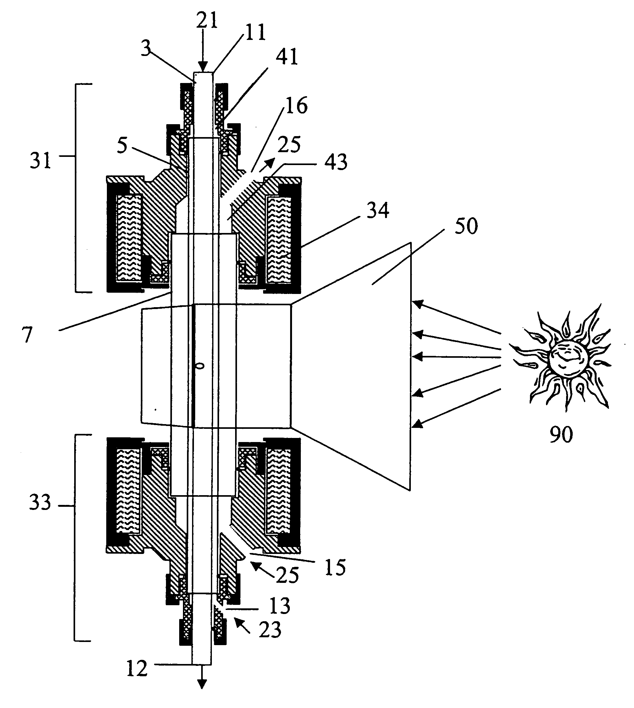
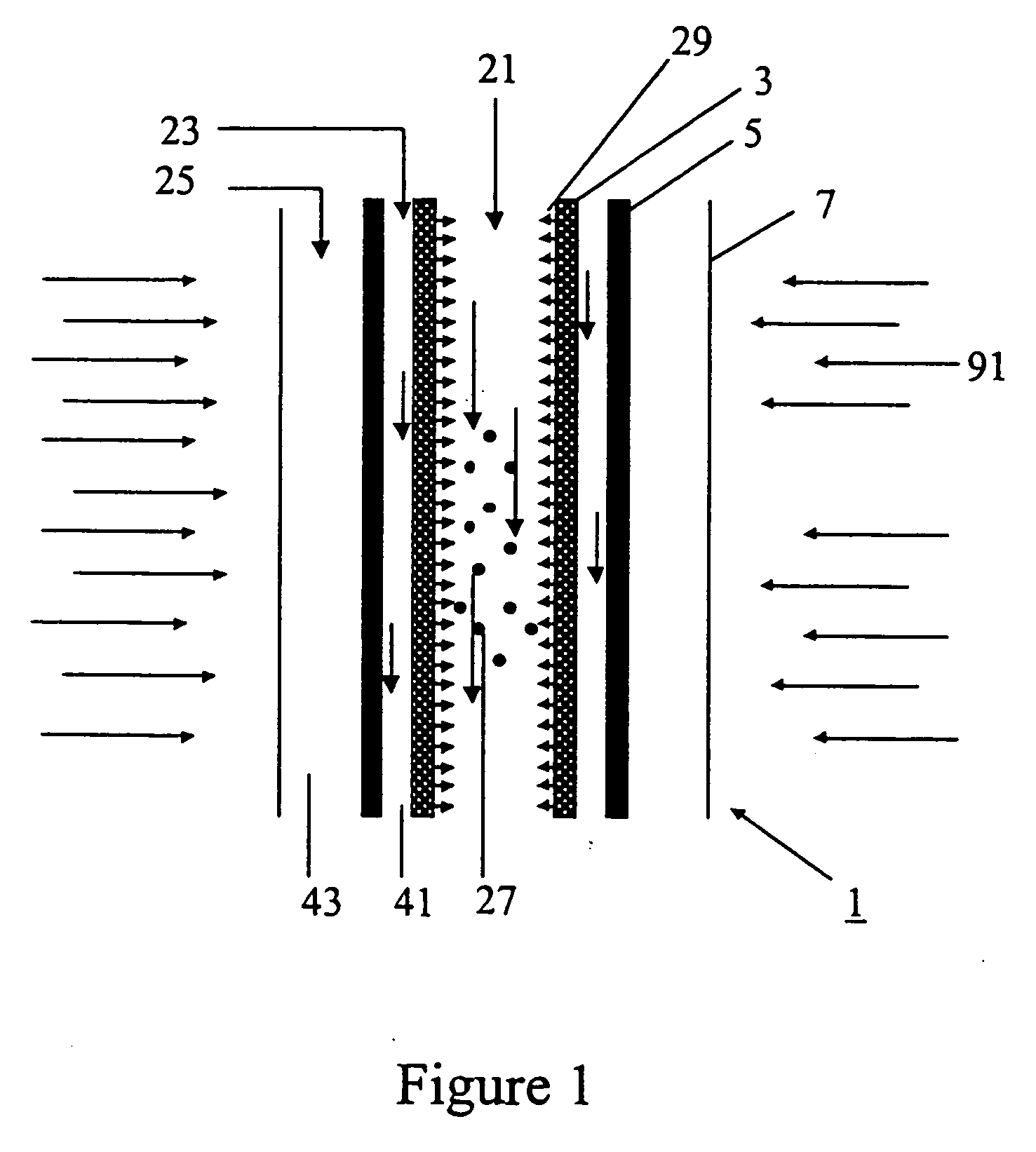
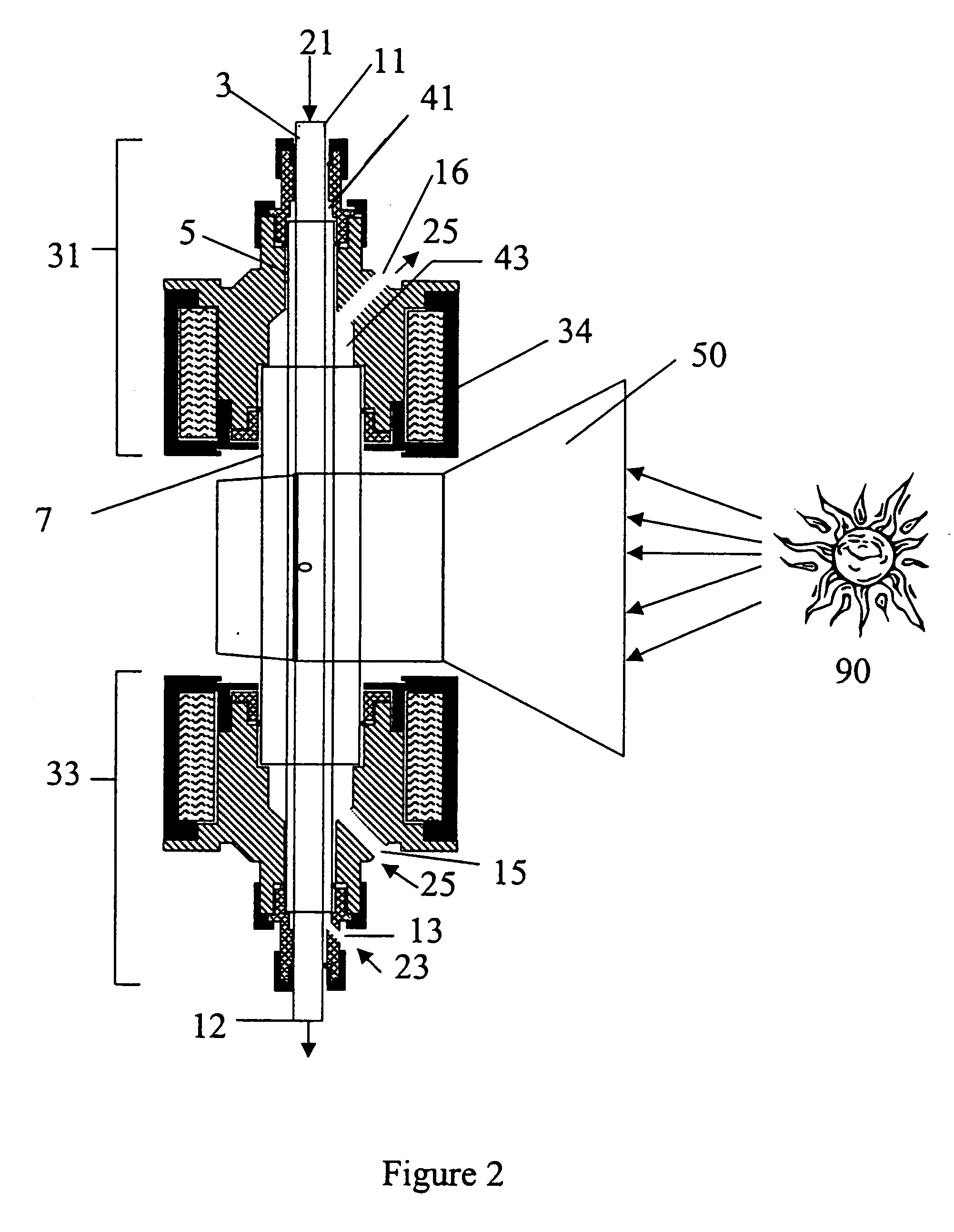
[0088] In accordance with the present invention, a concentric three-tube aerosol transport reactor was constructed and vertically interfaced to the HFSF at NREL. The aerosol transport reactor consisted of an outer 5.1 cm outside diameter×4 mm thick×24 cm long quartz “protection” tube, a central 2.4 cm outside diameter×4 mm thick×35.6 cm long graphite “heating” tube, and a 1.8 cm outside diameter×6 mm thick×44 cm long graphite “reaction” tube. The “reaction” tube consisted of a 30 cm long porous graphite section with 7 cm of solid graphite tube on both ends of the “reaction” tube. The porosity of the graphite tube was 49% with a permeability of air (at standard temperature and pressure (STP)) of 1 ft3 / ft2 / min. It was a sunny day. A secondary concentrator delivered 7.4 kW of solar-thermal power over a 9.4 cm length. The concentrator was positioned concentrically around the outer quartz “protection” tube. A 99% methane / 1% argon gas was fed at a rate o...

example 2

Operation of a Three-Shell Reactor with No “Fluid-Wall” Gas Flow

[0089] The process conditions of Example 1 were repeated except that no “fluid-wall” hydrogen gas was flowed through the porous “reaction” tube. Within 8 minutes, the process was shut down due to difficulties maintaining feed gas flow using mass flow controllers. After cooling, the reactor was dismantled and inspected. It was found that carbon was deposited inside of the “reaction” tube. The carbon was analyzed by x-ray diffraction and found to contain a large graphitic content. This comparative example illustrates that, without the fluid-wall, the reactor plugs and prevents continuous operation.

example 3

Reactor Operation with Increased Fluid-Wall and Purge Gas Flow Rates

[0090] The apparatus described in Example 1 was used except that the “fluid-wall” gas was changed to argon. It was fed at a rate of 4 slpm through the porous tube wall. In addition, the argon “purge” gas flow was increased to 10 slpm.


PUM

PropertyMeasurementUnit
temperaturesaaaaaaaaaa
temperatureaaaaaaaaaa

Abstract

The present invention provides a method for carrying out high temperature thermal dissociation reactions requiring rapid-heating and short residence times using solar energy. In particular, the present invention provides a method for carrying out high temperature thermal reactions such as dissociation of hydrocarbon containing gases and hydrogen sulfide to produce hydrogen and dry reforming of hydrocarbon containing gases with carbon dioxide. In the methods of the invention where hydrocarbon containing gases are dissociated, fine carbon black particles are also produced. The present invention also provides solar-thermal reactors and solar-thermal reactor systems.

Description

CROSS-REFERENCE TO RELATED APPLICATIONS [0001] This application is a divisional application of U.S. patent application Ser. No. 10 / 383,875, filed Mar. 7, 2003, which takes priority from U.S. provisional application Ser. No. 60 / 362,563, filed Mar. 7, 2002, and which is a continuation-in-part of application Ser. No. 10 / 239,706 filed Feb. 24, 2003, which is the national stage of PCT application number PCT / US01 / 15160 filed May 8, 2001, which claims the benefit of U.S. provisional application No. 60 / 203,186, filed May 8, 2000.ACKNOWLEGEMENT OF GOVERNMENT SUPPORT [0002] This invention was made, at least in part, with funding from the United States Department of Energy under grant numbers DE-FC36-99G010454 and DE-AC36-99G010337. The United States Government has certain rights in this invention.BACKGROUND OF THE INVENTION [0003] The present invention relates to solar-thermal reactors and processes for carrying out high temperature chemical reactions. More particularly, it relates to a rapid...

Claims


Application Information

Patent Timeline
Patent Type & Authority Applications(United States)
IPC IPC(8): C09C1/48B01J8/00B01J8/02B01J8/08B01J10/00B01J19/12C01B3/04C01B3/24C01B3/34C01B17/04F24S20/20F28C3/12
CPCC01B2203/04C01B2203/049C01B2203/0805C01B2203/0833C01B2203/085C01B2203/0866C09C1/48F24J2/07F28C3/12Y02E10/41Y02E60/364B01J8/0045B01J8/025B01J8/087B01J10/002B01J19/127B01J2208/00212B01J2208/0038B01J2208/00451B01J2208/00513B01J2208/00522B01J2208/00752B01J2219/00006B01J2219/0272B01J2219/0883C01B3/04C01B3/24C01B3/34C01B3/344C01B17/0495C01B2203/0216C01B2203/0222C01B2203/0272F24S20/20Y02E10/40Y02E60/36Y02P20/133C01P2006/80
Inventor WEIMER, ALAN W.DAHL, JAIMEE K.LEWANDOWSKI, ALLAN A.BINGHAM, CARLBUECHLER, KAREN J. RASKAGROTHE, WILLY
Owner UNIV OF COLORADO THE REGENTS OF
Why Eureka
Try Eureka