Method of manufacturing expansile filamentous embolization devices

a filamentous embolization and filament technology, applied in the field of body cavity occlusion devices, can solve the problems of balloon rupture during inflation, difficult visualization, and difficult to retrieve or move after solidifying fluid sets, and achieve the effects of promoting effective embolization, excellent location control, and reducing the risk of vascular ruptur

Inactive Publication Date: 2006-07-06
MICROVENTION INC
View PDF64 Cites 41 Cited by
  • Summary
  • Abstract
  • Description
  • Claims
  • Application Information

AI Technical Summary

Benefits of technology

[0017] In a second preferred embodiment, the carrier comprises a continuous length of highly flexible, hollow microcoil made of a biocompatible metal (preferably platinum or platinum / tungsten alloy), with an optional core in the form of a continuous length of thin, highly flexible metal wire, preferably of a shape memory metal alloy such as Nitinol. Alternatively, the carrier may be a suitable length of flexible wire, cable, braid, or other construction that yields the desired flexibility. The carrier is preferably made of a biocompatible metal so as to be visible by means of X-rays or other visualization techniques known in the art, but it also may be made of a suitable polymer that is visible (or is rendered visible) through any of the known visualization methods. The carrier should have sufficient column strength to allow the device to be pushed through a microcatheter.
[0028] Moreover, in both the third and fourth exemplary embodiments of the device, the flexibility, size, and lubricity of the hydrophilic polymer of the coaxial member, and hence, the device itself, all increase with the degree of hydration of the polymer. In accordance with one exemplary embodiment of this invention, the rate of hydration of the polymer in an aqueous environment is, as described above, set during manufacture to a specific value in response to a corresponding specific level of a physical parameter of the environment, e.g., its pH level.
[0029] Thus, in one possible embodiment of a method for preparing a fully dehydrated device for insertion into a body cavity via a catheter, the dry device is first immersed in an aqueous medium, e.g., a saline solution, having a relatively low pH level, such that the rate of hydration of the coaxial polymer member in the medium is correspondingly slow. This increases the flexibility and lubricity of the device such that it can be easily inserted into and moved through the lumen of the catheter and into the body cavity, but at a rate that is slow enough to afford the physician ample time to implant the device without allowing it to expand to a size that cannot be inserted into or moved easily through the catheter. However, once the device is emplaced in the cavity, its rate of hydration increases substantially in response to the increased pH level of the surrounding physiological aqueous environment, i.e., blood or plasma, such that the coaxial embolizing member of the device then expands correspondingly rapidly to occlude the cavity.
[0042] The present invention provides a number of significant advantages. Specifically, the present invention provides an effective body cavity or vascular embolization device that can be deployed within a cavity or vascular site with excellent locational control, and with a lower risk of vascular rupture, tissue damage, or migration than with prior art devices. Furthermore, the embolization device effects a conformal fit within the site that promotes effective embolization, and yet its ability to be delivered to the site through a microcatheter facilitates precise and highly controllable deployment. In addition, the essentially filamentous initial configuration of the embolization device, whereby it readily conforms to the interior dimensions of the target site, allows it to be used effectively to embolize body cavities having a wide variety of sizes, configurations, and (in the particular case of aneurysms) neck widths. These and other advantages will be readily appreciated from the detailed description that follows.

Problems solved by technology

While the balloon-type embolization device can provide an effective occlusion of many types of aneurysms or other body cavities, it is difficult to retrieve or move after the solidifying fluid sets, and it is difficult to visualize unless it is filled with a contrast material.
Furthermore, there are risks of balloon rupture during inflation and of premature detachment of the balloon from the catheter.
The direct injection of liquid polymer embolic agents has proven difficult in practice.
For example, migration of the polymeric material from the aneurysm and into the adjacent blood vessel has presented a problem.
In addition, visualization of the embolization material requires that a contrasting agent be mixed with it, and selecting embolization materials and contrasting agents that are mutually compatible may result in performance compromises that are less than optimal.
Furthermore, precise control of the deployment of the polymeric embolization material is difficult, leading to the risk of improper placement and / or premature solidification of the material.
Moreover, once the embolization material is deployed and solidified, it is difficult to move or retrieve.
Microcoils have been less successful in the treatment of larger aneurysms, especially those with relatively wide necks.
A disadvantage of microcoils is that they are not easily retrievable; if a coil migrates out of the aneurysm, a second procedure to retrieve it and move it back into place is necessary.
Furthermore, complete packing of an aneurysm using microcoils can be difficult to achieve in practice.
Nevertheless, as in conventional microcoil techniques, the successful use of the GDC procedure has been substantially limited to small aneurysms with narrow necks.
These materials are delivered as microparticles in a carrier fluid that is injected into the vascular site, a process that has proven difficult to control.
These types of plugs or implants are primarily designed for obstructing blood flow through a tubular vessel or the neck of an aneurysm, and they are not easily adapted for precise implantation within a sac-shaped vascular structure, such as an aneurysm, so as to fill substantially the entire volume of the structure.
Because there is no mechanical connection between the pellets and the guidewire (other than the relatively weak temporary bond provided by the restraining agent), however, premature release and migration of some of the pellets remains a possibility.
There has thus been a long-felt, but as yet unsatisfied need for a device for effective occlusive treatment of aneurysms and other body cavities, and a method that can substantially fill aneurysms and other body cavities of a large range of sizes, configurations, and neck widths with an occlusive and / or thrombogenic medium with a minimal risk of inadvertent tissue damage, aneurysm rupture or blood vessel wall damage.

Method used


Image

  • Method of manufacturing expansile filamentous embolization devices
  • Method of manufacturing expansile filamentous embolization devices
  • Method of manufacturing expansile filamentous embolization devices

Examples


second embodiment

[0096] The Embolization Device: Second Preferred Embodiment. FIGS. 14 through 23 illustrate an embolization device in accordance with a second preferred embodiment of the present invention. Referring first to FIGS. 14 through 17, a device 100 in accordance with this second embodiment comprises an elongate, flexible, filamentous carrier 102 on which an expansile embolizing element 104 is non-releasably carried. The carrier 102 is preferably formed from a continuous length of hollow microcoil 106, made from a suitable metal such as platinum, gold, tungsten, or tantalum, or a metallic alloy, such as stainless steel or Nitinol. Of these materials, platinum and Nitinol are preferred. The microcoil is formed with tightly-packed coils, so that there is little or no spacing between adjacent coils. The carrier 102 may also include a filamentous core 108 extending axially through the microcoil 106. The core 108 is a thin metal wire, preferably made of a shape memory metal such as Nitinol. The...

third embodiment

[0115] The Embolization Device: Third Exemplary Embodiment and First Method for Making It: A third exemplary embodiment of a device 300 for occluding a body cavity is illustrated in FIGS. 32-35, and a first exemplary embodiment of a method for making the device 300 is illustrated in FIGS. 24-31.

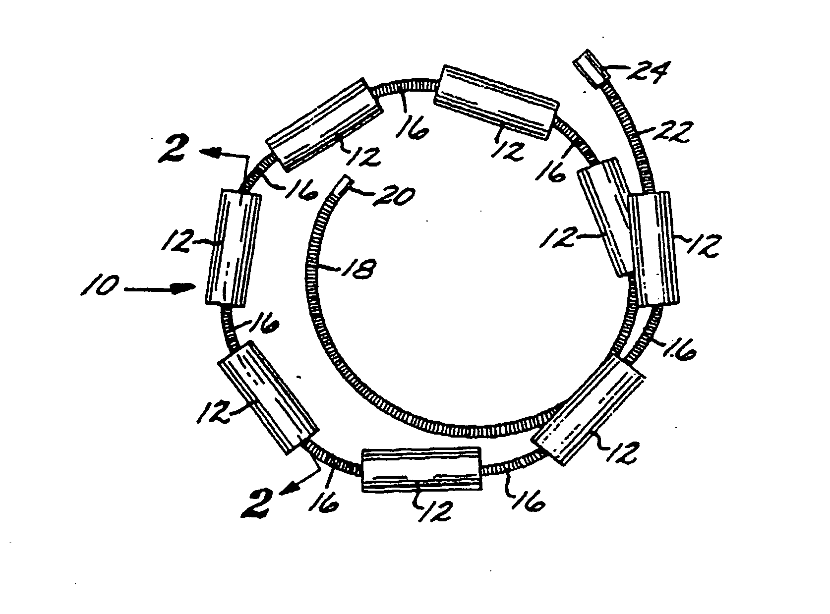
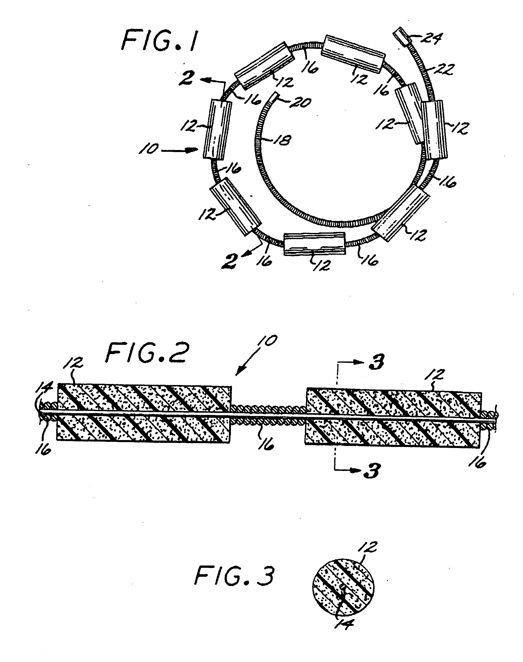
[0116] As shown in FIG. 32, the embolization device 300 comprises an elongated, filamentous carrier 302, and an embolizing element comprising a coaxial member 304 of an expansile, hydrophilic polymer, or hydrogel, described in detail above, encapsulating at least a portion of the length of the carrier.

[0117] Although the coaxial polymer embolizing member 304 is shown in the figures as having a substantially cylindrical shape, it should be understood that the member, and indeed, the carrier encapsulated within it, can have a wide variety of other cross-sectional shapes, e.g., polygonal, longitudinally grooved, and the like, depending on the particular application at hand.

[0118] The carrier 3...

fourth embodiment

[0126] The Embolization Device: Fourth Exemplary Embodiment and Second Method for Making It: A fourth exemplary embodiment of an embolization device 400 for occluding a body cavity is illustrated in FIGS. 39-42, and a second exemplary embodiment of a method for making the device 400 is illustrated in FIGS. 36-38.

[0127] As illustrated in FIGS. 39 and 41, respectively, two possible variants of the fourth exemplary embodiment of embolization device 400 both comprise, as in the case of the third exemplary embodiment 300 described above, an elongated, filamentous carrier 402, and a coaxial member 404 of an expansile, hydrophilic polymer, or hydrogel, encapsulating at least a portion of the length of the carrier. Further, in both variants, the carrier 402 may, like the third embodiment above, comprise either an elongated strand of a flexible, biocompatible material, e.g., platinum wire, or a flexible tube.

[0128] However, in contrast to the third embodiment of the device 300 above, in the...


PUM

PropertyMeasurementUnit
diameteraaaaaaaaaa
diameteraaaaaaaaaa
diameteraaaaaaaaaa

Abstract

An embolization device for occluding a body cavity includes one or more elongated, expansible, hydrophilic embolizing elements non-releasably carried along the length of an elongated filamentous carrier that is preferably made of a very thin, highly flexible filament or microcoil of nickel / titanium alloy. At least one expansile embolizing element is non-releasably attached to the carrier. A first embodiment includes a plurality of embolizing elements fixed to the carrier at spaced-apart intervals along its length. In second, third and fourth embodiments, an elongate, continuous, coaxial embolizing element is non-releasably fixed to the exterior surface of the carrier, extending along a substantial portion of the length of the carrier proximally from a distal tip, and optionally includes a lumenal reservoir for delivery of therapeutic agents. Exemplary methods for making these devices include skewering and molding the embolizing elements. In any of the embodiments, the embolizing elements may be made of a hydrophilic, macroporous, polymeric, hydrogel foam material. In the second, third and fourth embodiments, the elongate embolizing element is preferably made of a porous, environmentally-sensitive, expansile hydrogel, which can optionally be made biodegradable and / or bioresorbable, having a rate of expansion that changes in response to a change in an environmental parameter, such as the pH or temperature of the environment.

Description

CROSS REFERENCE TO RELATED APPLICATIONS [0001] This application is a Continuation-in-Part of co-pending application Ser. No. 09 / 867,340, filed May 29, 2001, which is a Continuation-in-Part of co-pending application Ser. No. 09 / 542,145, filed Apr. 4, 2000, now U.S. Pat. No. 6,299,619, issued Oct. 9, 2001, which is a Continuation-in-Part of application Ser. No. 09 / 410,970, filed Oct. 4, 1999, now U.S. Pat. No. 6,238,403, issued May 29, 2001.FEDERALLY SPONSORED RESEARCH OR DEVELOPMENT [0002] Not Applicable BACKGROUND OF THE INVENTION [0003] The present invention relates to devices for the occlusion of body cavities, such as in the embolization of vascular aneurysms and the like, and methods for making and using such devices. More specifically, the present invention relates to a device that is inserted into a body cavity, such as an aneurysm, to occlude the cavity by creating an embolism therein, a method for making the device, and a method for embolizing a body cavity using the device....

Claims


Application Information

Patent Timeline
Patent Type & Authority Applications(United States)
IPC IPC(8): A61B17/08A61B17/00A61B17/12A61L29/00A61L31/02A61L31/14A61L31/18A61M25/00B29C70/74
CPCA61B17/12022A61B17/12113A61B17/12118A61B17/12145A61B17/12154A61B17/12163A61B17/1219A61B2017/00004A61B2017/00526A61B2017/1205A61L31/022A61L31/145A61L31/18A61L2430/36B29C70/74B29L2031/7542
Inventor GREENE, GEORGE R. JR.CRUISE, GREGORY M.CONSTANT, MICHAELCOXTRAN, TERRANCE
Owner MICROVENTION INC
Why Eureka
Try Eureka