Arrays of electrodes coated with molecules and their production

a technology of electrodes and molecules, applied in the direction of electrophoretic coatings, isotope separation, electrophoretic coatings, etc., can solve the problems of limiting the applicability of this procedure for nanoscale assembly, speed and the ability to coat different electrodes individually, and not meeting the requirements of resolution, speed and the ability to achieve spatial resolution, high purity, and reduced contamination

Inactive Publication Date: 2006-07-13
CAMBRIDGE UNIV TECH SERVICES LTD
View PDF2 Cites 20 Cited by
  • Summary
  • Abstract
  • Description
  • Claims
  • Application Information

AI Technical Summary

Benefits of technology

[0019] We find that the process has the advantage of allowing formation of arrays of a large number of different coating molecules coated with high purity at nanoscale resolution. In particular, we find that use of an array of individually-addressable electrodes has significant advantages over the method described by Wilhelm et al (which induces desorption from different regions of a single electrode) that resolution can be greater and effects on regions neighbouring the electrodes can be controlled to avoid unwanted desorption.
[0020] Step (e) is particularly important...

Problems solved by technology

However, the selective multiple coating of electrode arrays with appropriate anchor molecules has not yet been demonstrated on structures where the electrode separations are sub-micrometre, limiting the applicability of this procedure for nanoscale assembly.
A number of techniques are available for introducing oligonucleotides or other anchor molecules locally onto a surface, but none of these simultaneously meet the requirements of resolution, speed and the ability to coat different electrodes uniquely.
Micromachining and microcontact printing offer spatial resolutions of several hundred nanometres but lack the ability to effect multiple coating.
A much higher resolution (a few tens of nanometres) has been achieved by nanografting, but this technique i...

Method used


Image

  • Arrays of electrodes coated with molecules and their production
  • Arrays of electrodes coated with molecules and their production
  • Arrays of electrodes coated with molecules and their production

Examples


examples

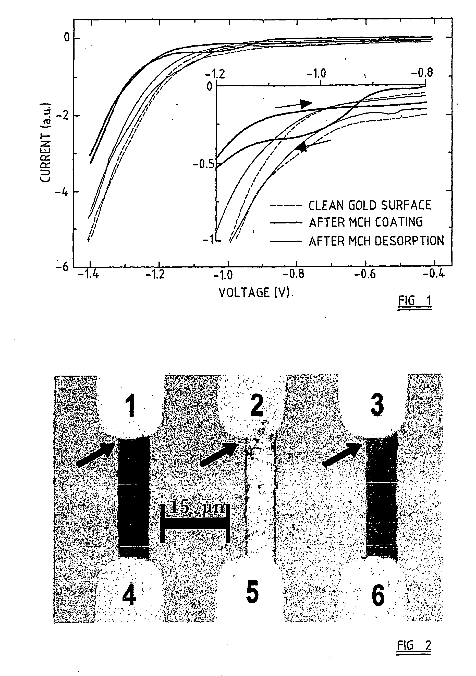
[0061] A series of opposing gold electrodes of sub-50 nm-separation was fabricated on a Si / SiO2 wafer using known UV lithography / lift off techniques as described below. The wafer was cleaned by washing in ‘piranha etch’ (30% H2O2, 70% H2SO4) for 1 hour, and then thoroughly rinsed in deionised water, ethanol, and again in deionised water. The entire electrode array was then coated with a protective molecular monolayer of 6-mercapto-1-hexanol (MCH) by immersing the wafer in a 1 mM aqueous solution of MCH for 60 min. FIG. 1 compares the CV trace of a coated electrode (solid line) with that of a clean electrode prior to coating (dashed line). A reductive desorption feature observed at around −1 V for the coated electrode indicates the removal of the MCH monolayer. All electrochemical measurements were performed in 100 mM phosphate buffer at pH 10 using a standard three electrode setup at a rate of 62 mV / s. A high purity platinum wire was used as the counter electrode. All electrochemica...


PUM

PropertyMeasurementUnit
Diameteraaaaaaaaaa
Lengthaaaaaaaaaa
Distanceaaaaaaaaaa

Abstract

The present invention provides a method of forming coatings of at least two different coating molecules on at least two electrodes, the method comprising: (a) providing an array of at least two individually-addressable electrodes, (b) allowing a layer of a masking molecule to adsorb onto all electrodes, (c) inducing electrochemical desorption of the masking molecule from at least one but not all electrodes to expose a first set of exposed electrodes, (d) allowing a first coating molecule to adsorb onto the first set of exposed electrodes, (e) exposing all electrodes to a masking molecule to allow adsorption of the masking molecule onto all electrodes, (f) inducing electrochemical desorption of masking molecule from a second set of electrodes to expose a second set of exposed electrodes, (g) allowing a second coating molecule to adsorb onto the second set of exposed electrodes.

Description

FIELD OF THE INVENTION [0001] The invention relates to methods for production of arrays of a number of different coating molecules by forming coatings on a number of different electrodes. It also relates to arrays of molecules produced by these methods. BACKGROUND OF THE INVENTION [0002] Among the many challenges facing the development of a molecular-based nanotechnology, the directed assembly of discrete molecular objects, and their controlled integration into macroscopic structures, are fundamental. The selective self-assembly characteristic inherent to certain molecules (for example, the Watson-Crick specific base pairing that occurs between complementary single strands of DNA) is a property that could be exploited to address these challenges. For example, ordered suspensions of gold nanoparticles have been assembled by first functionalizing the nanoparticles with short DNA oligonucleotides and then introducing complementary DNA to tie the individual particles together as the str...

Claims


Application Information

Patent Timeline
IPC IPC(8): C25D13/00B01J19/00C12Q1/68C12Q1/6837C40B40/06C40B60/14
CPCB01J19/0046B01J2219/00427B01J2219/005B01J2219/00529B01J2219/00596B01J2219/00608B01J2219/00612B01J2219/00626B01J2219/00637B01J2219/00648B01J2219/00653B01J2219/00659B01J2219/00722B82Y30/00C12Q1/6837C40B40/06C40B60/14C12Q2565/607
Inventor DAVIES, ALEXANDER GILESWALTI, CHRISTOPHMIDDLEBERG, ANTON PETER JACOBPEPPER, MICHAELWIRTZ, RENE
Owner CAMBRIDGE UNIV TECH SERVICES LTD
Why Eureka
Try Eureka