
Resist composition, multilayer body, and method for forming resist pattern

Active Publication Date: 2006-07-13
TOKYO OHKA KOGYO CO LTD
View PDF27 Cites 2 Cited by
  • Summary
  • Abstract
  • Description
  • Claims
  • Application Information

AI Technical Summary

Benefits of technology

[0206] As described above, in the present invention, a shrink process in which a treatment such as heating is conducted following formation of a resist pattern to effect a narrowing of the resist pattern can be used for forming a favorable resist pattern, meaning the present invention is extremely useful industrially.

Problems solved by technology

However, these resins exhibit unsatisfactory transparency near 193 nm.
However, in this type of thermal flow process, because the resist is caused to flow by heating conducted after the developing step, a problem arises in that the cross-sectional shape of the side walls of the resist pattern are prone to collapse, causing a deterioration in the verticalness (rectangularity) of the pattern.
However, until now, the resists used in shrink processes have been i-line or KrF resists, and if the same shrink processes are used with resists that include a resin containing structural units derived from methacrylate ester units as the primary units, such as the resins used within ArF resists, then the merits of the shrink process in enabling miniaturization of the resist pattern are difficult to achieve.

Method used


Image

  • Resist composition, multilayer body, and method for forming resist pattern
  • Resist composition, multilayer body, and method for forming resist pattern
  • Resist composition, multilayer body, and method for forming resist pattern

Examples


example 1

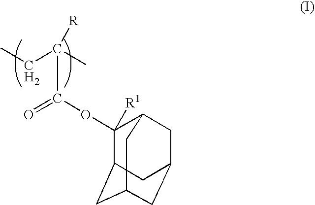
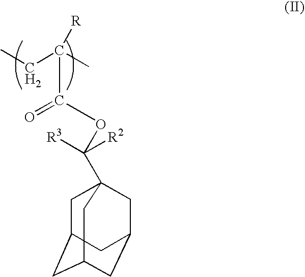
[0186] 0.25 mols of a 30 / 50 / 20 (molar ratio) mixture of 2-ethyl-2-adamantyl acrylate, norbomane lactone acrylate of the general formula (i) (wherein R is a hydrogen atom), and 3-hydroxy-1-adamantyl acrylate of the general formula (VI) (wherein R is a hydrogen atom) was dissolved in 500 ml of methyl ethyl ketone (MEK), and 0.01 mols of AIBN was then added to the solution and dissolved. The thus obtained solution was heated to a temperature of 65 to 70° C., and maintained at this temperature for 3 hours. Subsequently, the reaction solution was poured into 3 L of vigorously stirred isopropanol, and the precipitated solid was isolated by filtration. The thus obtained solid product was dissolved in 300 ml of MEK, poured into 3 L of vigorously stirred methanol, and once again the precipitated solid was isolated by filtration and then dried, yielding a resin X for which the weight average molecular weight (Mw)=10,000, Mw / Mn=2.0, and Tg =approximately 130° C. 0.25 mols of a 40 / 40 / 20 (molar ...

example 2

[0196] With the exception of replacing the component (A) of the example 1 with a single copolymer (a resin Z, for which weight average molecular weight (Mw)=10,000, Mw / Mn=1.9, and Tg=approximately 160° C.), which was produced from a 40 / 40 / 20 (molar ratio) mixture of 2-ethyl-2-adamantyl methacrylate, norbomane lactone acrylate of the general formula (i) (wherein R is a hydrogen atom), and 3-hydroxy-1-adamantyl acrylate of the general formula (VI) (wherein R is a hydrogen atom) using the same method as the example 1, a positive resist composition was prepared in the same manner as the example 1.

[0197] Subsequently, with the exception of altering the PEB temperature to 90° C., a resist pattern was formed in the same manner as the example 1, thereby yielding a hole pattern with a hole diameter of 140 nm.

[0198] Finally, when a shrink process using a water-soluble coating was conducted in the same manner as the example 1, the size of the hole pattern was reduced by approximately 20 nm, ...


PUM

PropertyMeasurementUnit
Temperatureaaaaaaaaaa
Solubility (mass)aaaaaaaaaa

Abstract

A resist composition is disclosed that enables formation of a favorable resist pattern using a shrink process in which, following formation of the resist pattern, a treatment such as heating is used to narrow the resist pattern, and also disclosed are a laminate and a method for forming a resist pattern that use such a resist composition. This resist composition includes a resin component (A) that displays changed alkali solubility under the action of acid, and an acid generator component (B) that generates acid on exposure. The component (A) contains structural units derived from a (meth)acrylate ester, and exhibits a glass transition temperature that falls within a range from 120 to 170° C.

Description

TECHNICAL FIELD [0001] The present invention relates to a resist composition that can be used favorably in a method for forming a resist pattern in which, following formation of a resist pattern on a support, a shrink process is conducted wherein a water-soluble coating formed from a water-soluble coating formation agent containing a water-soluble polymer is provided on top of the resist pattern, and this water-soluble coating is then shrunk by heating, thereby narrowing the spacing of the resist pattern, and also relates to a laminate and a method for forming a resist pattern that use such a resist composition. [0002] Priority is claimed on Japanese Patent Application No. 2003-194256, filed Jul. 9, 2003, the content of which is incorporated herein by reference. BACKGROUND ART [0003] In recent years, in the production of semiconductor elements and liquid crystal display elements, advances in lithography techniques have lead to rapid progress in the field of miniaturization. Typicall...

Claims


Application Information

Patent Timeline
IPC IPC(8): G03C1/76C08F220/18C08F220/26G03F7/039G03F7/40H01L21/027
CPCG03F7/0397G03F7/40Y10S430/106Y10S430/111G03F7/039
Inventor HADA, HIDEOSASAKI, KAZUHITOFUJIMURA, SATOSHIIWAI, TAKESHI
Owner TOKYO OHKA KOGYO CO LTD
Learn More