Organic transistor and manufacturing method thereof

a manufacturing method and organic technology, applied in the direction of thermoelectric device junction materials, semiconductor devices, electrical apparatus, etc., can solve the problems of unrealistic as a process of manufacturing organic transistors, limited substrate materials, and difficulty in highly fine patterning, and achieve high electric characteristics, high free energy high-precision patterning, and high efficiency

Inactive Publication Date: 2006-07-20
CANON KK
View PDF16 Cites 30 Cited by
  • Summary
  • Abstract
  • Description
  • Claims
  • Application Information

AI Technical Summary

Benefits of technology

[0013] In a mode of the present invention, an object of the present invention is to realize an organic transistor having a short channel and high electric characteristics, which is formed by patterning of surface free energy with general UV light of 254 nm as UV light wavelength of an exposure system and, consequently, implements highly fine patterning of surface free energy with an inexpensive aligner. Moreover, another object of the present invention is to realize an organic transistor having a short channel and high electric characteristics and including a layer having a function of controlling orientation and a material excellent in insulating performance which are separated.
[0014] In addition, in another mode of the present invention, an object of the present invention is to accurately form a gate electrode by providing a substrate insulating layer on a substrate, subjecting the substrate insulating layer to highly fine patterning of surface free energy with UV light of 254 nm without using vacuum process or photolithography.

Problems solved by technology

Accordingly, in order to implement highly fine patterning of a surface free energy, significantly expensive stepper using a vacuum UV light of 200 nm or less has to be used, which is unrealistic as a process of manufacturing an organic transistors.
In addition, due to implementation of back surface exposure, a substrate material is expected to be limited due to the light-absorbing property of the substrate.
Moreover, highly fine patterning is slightly difficult due to implementation of exposure using the gate electrode as a mask in the back surface exposure.
In this case, in case of applying an orientated organic semiconductor to a channel portion, orientation cannot be controlled and sufficient electric performance that the semiconductor material has cannot be drawn out.
In addition, it is possible to design polyimide so that patterning of a surface free energy is implemented with UV light of 254 nm, which however occasionally gives rise to decrease in insulating performance.

Method used


Image

  • Organic transistor and manufacturing method thereof
  • Organic transistor and manufacturing method thereof
  • Organic transistor and manufacturing method thereof

Examples


experiment 1

(Experiment 1)

[0079] Relationship of density of alkyl group, surface free energy (surface E), surface free energy hydrogen bonding term, water repellency and leak current will be described in the following Table 1. Table 1 shows relationship of density of alkyl group, surface free energy, hydrogen bonding term, water repellency and leak current in respective kinds of insulating films which are applied for describing experiments of the present invention.

TABLE 1HydrogenInsulatingAlkylSurface EbondingWaterfilmgroup(mN / m)(mN / m)repellencyLeakANone503.1xBNone492.5x∘CNone452.0xΔDSmall401.0∘xdensityEMiddle370.2∘xdensityFLarge350.0xdensity

(Note 1:)

Evaluation of water repellent reads as follows.

: extremely well water-repellent.

∘: comparatively water-repellent.

x: not water-repellent.

(Note 2:)

Evaluation of leak reads as follows.

: Leak current is extremely small and gives rise to no problem as an insulating layer.

∘: Leak current is comparatively small and gives rise to no problem as an...

experiment 2

(Experiment 2)

[0082] Surface free energy of an insulating layer consisting of polyimide containing an alkyl group in a side chain was caused to undergo partial change, and an experiment on striking water droplets differently was implemented with an ink-jet method. Onto a portion of an insulating layer with surface free energy being sufficiently low and showing an initial contact angle of 95 degrees which was subjected to irradiation of UV light to partially increase surface free energy and decrease the contact angle, water droplets were made to drop by an ink-jet method, and it was determined whether or not the droplets after landing went over a portion having a low surface free energy. Table 2 shows a result thereof. Table 2 shows relationship between contact angle of water of polyimide after 254 nm UV light irradiation and the state of striking droplets differently, to be applied to description of an experiment of the present invention.

TABLE 2Contact angle of water(subject to UV...

experiment 3

(Experiment 3)

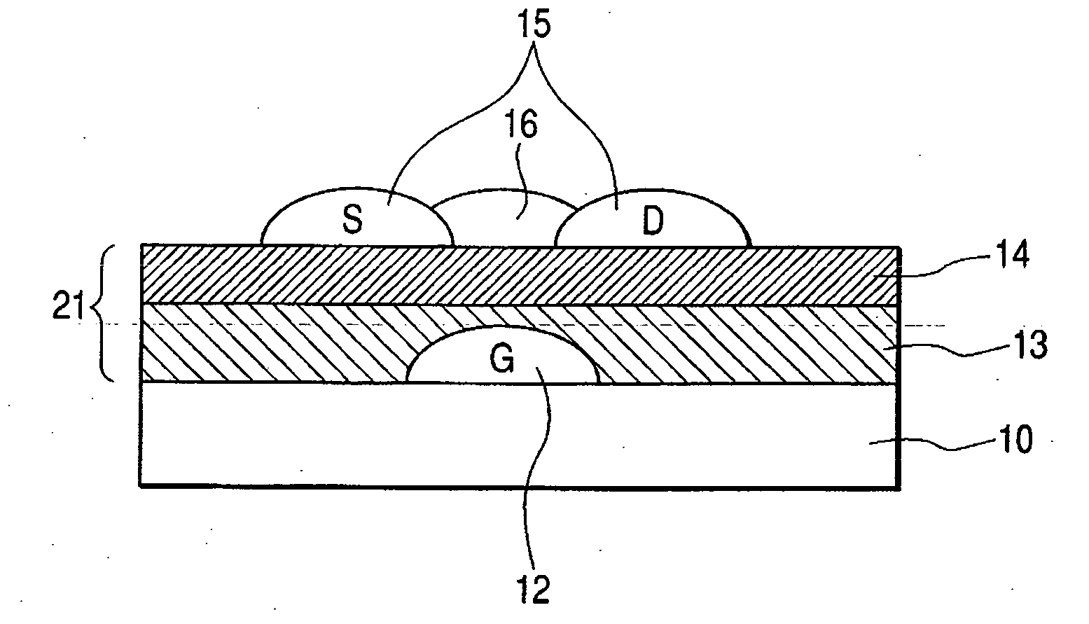
[0086] Based on a result of Experiments 1 and 2, a substrate insulating layer with surface free energy of 40 mN / m or less was subjected to patterning thereon with UV light to form a portion to become a gate electrode with surface free energy of 50 mN / m or more and to consider to what extent gate electrode width can be struck differently. Consideration was implemented with water as solvent. As in FIG. 16, a gate electrode portion of a substrate insulating layer-coating part 23 on a glass substrate 22 and, at the same time, portions sufficiently larger in width than the gate electrode on both sides of the gate electrode was subjected to UV exposure so as to make the surface free energy of the portions high to carry out patterning, and water was caused to drop with ink jet in the portions on both sides of the gate electrode. Since surface free energy in the portion to become the gate electrode is sufficiently high than its circumference, water soaks the gate electrode por...


PUM


Abstract

There is provided an organic transistor having a bottom gate structure, composed of a substrate, a gate electrode, a gate insulating layer, source and drain electrodes and an organic semiconductor layer, wherein the gate insulating layer is formed so as to have a low surface energy in a portion thereof in proximity to the source and drain electrodes and a relatively high surface energy in a portion in proximity to the gate electrode, and consist of different compositions in a layer thickness direction, whereby an organic transistor has a short channel and high electric characteristics; as well as a method of manufacturing the organic semiconductor.

Description

[0001] This application is a continuation of International Application No. PCT / JP2005 / 020399 filed on Nov. 1, 2005, which claims the benefit of Japanese Patent Application No. 2004-319737 filed on Nov. 2, 2004.BACKGROUND OF THE INVENTION [0002] 1. Field of the Invention [0003] The present invention relates to an organic transistor having an organic semiconductor material and a manufacturing method thereof, and specifically to an organic transistor formed by ink-jet drawing process and a manufacturing method thereof. [0004] 2. Related Background Art [0005] In recent years, research on organic electronic devices using organic materials has been flourishing. Realization of costly inexpensive organic electronic devices that are excellent in lowering process temperature and portability is expected by applying thin film formation of organic materials to devices. [0006] For example, research on organic electronic devices such as organic ELs and organic transistors etc. is flourishing. Amon...

Claims


Application Information

Patent Timeline
Patent Type & Authority Applications(United States)
IPC IPC(8): H01L29/08H01L21/84
CPCH01L51/0022H01L51/0541H01L51/0545H10K71/611H10K10/464H10K10/466
Inventor WADA, TAKATSUGUTOKUNAGA, HIROYUKIKANOME, OSAMUHANADA, MIKANISHIDA, TAKEHITO
Owner CANON KK
Why Eureka
Try Eureka