Interface patch clamping

Inactive Publication Date: 2006-07-27
GE HEALTHCARE LTD
View PDF13 Cites 3 Cited by
  • Summary
  • Abstract
  • Description
  • Claims
  • Application Information

AI Technical Summary

Benefits of technology

[0004] The proposed device in accordance with the present invention comprises a penetrative, optionally, non-return, intracellular electrical access electrode assembly, optionally doped with a sealing compound to prevent ionic leakage. It improves over existing electrode designs in the public domain in that it permits electrode entry for multiple recording at points both inside and outside of cells. It is able to be used such that cells can be manipulated in arrays and brought into contact with electrodes in a controlled manner prior to an automatic gaining of intracellular access. The device is able to be fitted to industry-standard robots to enable large-scale drug profiling applications.
[0005] The advantages of this device are in the coupling of the initial cell holding step to the cell penetration step that gives full transmembranal electrical access. This may be achieved by making the cell membrane ‘bow’ inwards towards the electrodes only under seal conditions and this allows cell penetration by recessed electrode(s): Embodiments of the present invention may have multipoint conductor electrodes, penetrating barbs, independent electrodes and / or doped local lipolysis for access. The use of a lipolytic agent, for example a needle or contact patch made of, or coated with, a conducting lipolytic polymer, is particularly useful to aid electrical access. Optionally, a non-ionically conducting sealing compound to prevent ionic leakage may be used.

Problems solved by technology

The use of penetrative electrodes on cells has been hampered by difficulties in holding individual cells in place prior to electrode insertion.

Method used


Image

  • Interface patch clamping
  • Interface patch clamping
  • Interface patch clamping

Examples


first embodiment

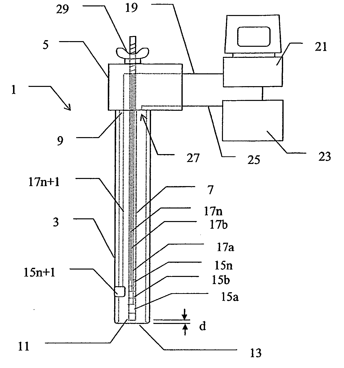
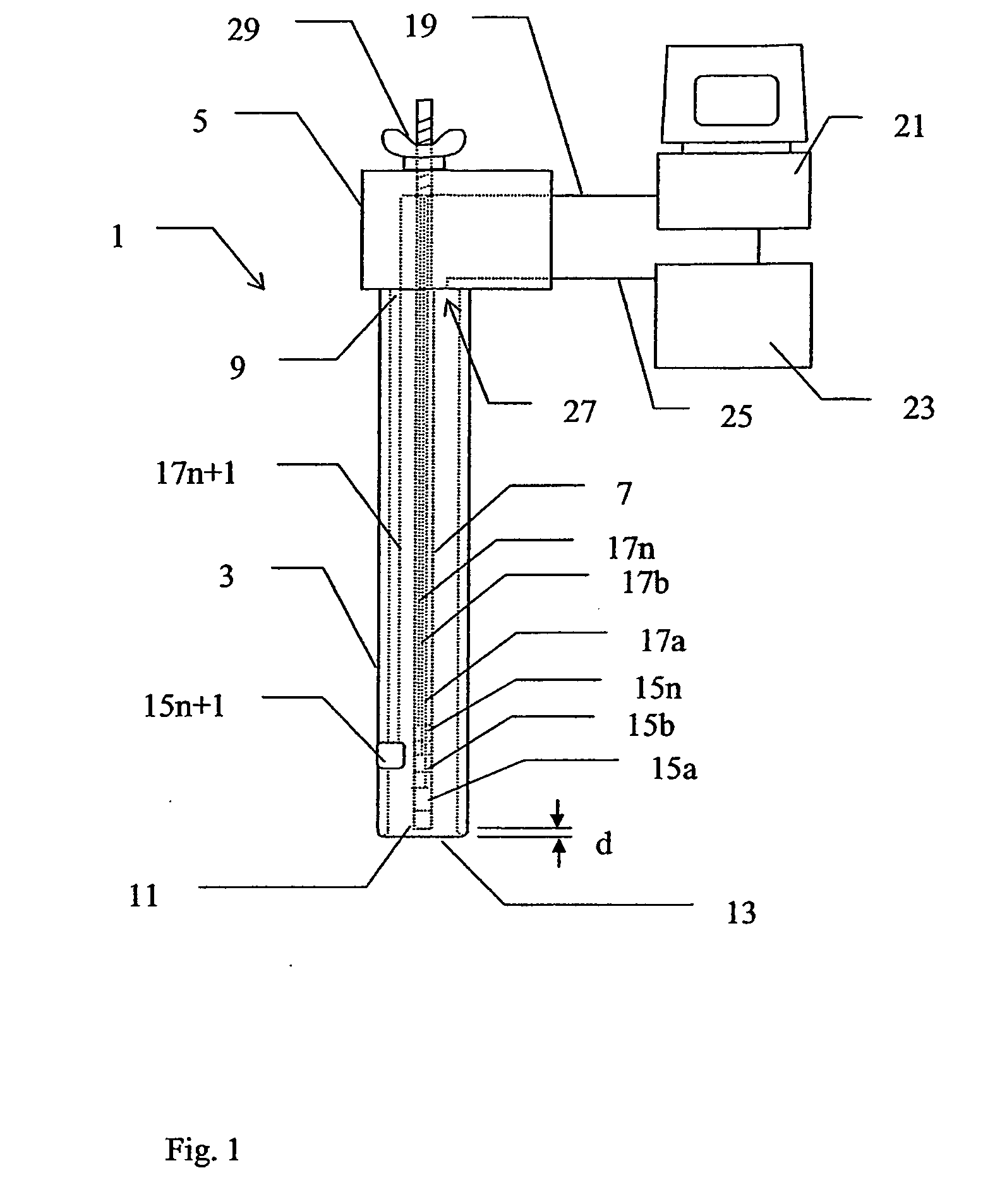
[0014]FIG. 1 shows schematically, and not to scale, an intracellular electrical access electrode assembly 1 according to the present invention. Electrode assembly 1 comprises a hollow, elongated, tubular electrode sheath 3 which projects out of an electrode assembly body 5. Electrode assembly body 5 is intended to be gripped by an operator or mounted on, or gripped by, a robot or to be attached to a movable carriage (not shown) in an automated analysis instrument and it can have any suitable shape. Preferably it is provided with docking features (not shown) such as specially shaped or positioned holes or projections which enable it to be accurately mounted on an automated manipulating device such as a robot arm or carriage or the like. An elongated electrode needle 7 is concentrically mounted inside electrode sheath 3. One end 9 of electrode needle 7 in held in electrode body 5 and the other, free, end 11 of electrode needle 7 is positioned either level with the open tip 13 of elect...

third embodiment

[0022] A schematic part view of an electrode assembly in accordance with the present invention is shown in FIG. 4. This electrode assembly comprises a plurality of electrode needles 7a-7n arranged inside the electrode sheath 3. Each electrode needle 7a-7n is provided with its own tip electrode 15a-15n. Optionally each electrode needle may be provided with a further ring or spot electrode (not shown). Additionally, the individual electrode needles 7a-7n may optionally be joined together, or optionally surrounded by a strengthening tube 49 (shown by dashed lines), along at least a part of their lengths in order to strengthen them and prevent buckling of the individual electrode needles 7a-7n. Each electrode needle may be provided with an individual barb and / or surface provided with non-ion-conducting sealing compound or, as shown in FIG. 4, only the electrode needles 7a, 7b, intended to penetrate the cell membrane, are each provided with a barb 43 and sealing compound 45.

[0023] In use...


PUM

PropertyMeasurementUnit
Electrical conductoraaaaaaaaaa

Abstract

The present invention relate to methods and devices for holding a cell and positioning recording electrodes inside it.

Description

FIELD OF THE INVENTION [0001] The present invention relates to devices of the type mentioned in the preambles of the independent claims for holding living cells for recording purposes. PRIOR ART [0002] Studies of the electrophysiology of cells involve measuring the flow of ionic current across the cell membrane inducing, or in response to, trans membrane conductance changes. One method of performing this involves holding a cell, penetrating the cell membrane with 1 or 2 microelectrodes and measuring the electrical signals detected by the microelectrode(s). A problem with such studies is that the cell-penetrating needles have been difficult to make and handle and that it has been difficult to hold the cell without harming it while inserting the electrode. Japanese patent application 11-299496 describes a method for inserting a microelectrode into an oocyte in which an oocyte is positioned in or on a container which is provided with microelectrode guiding means. The microelectrode gui...

Claims


Application Information

Patent Timeline
IPC IPC(8): G01N33/487G01N27/30
CPCG01N33/48728Y10S435/817C12M1/34G01N27/30G01N33/48707
Inventor CONLEY, EDWARD C.
Owner GE HEALTHCARE LTD
Why Eureka
Try Eureka