Resonant cavity biosensor

a biosensor and resonance cavity technology, applied in laboratory glassware, fluorescence/phosphorescence, optical radiation measurement, etc., can solve the problems of adversely affecting the binding properties, real-time operations, and failure to provide high throughput of date, so as to avoid the complexity of metals and high throughput

Inactive Publication Date: 2006-08-17
TRUSTEES OF BOSTON UNIV
View PDF8 Cites 97 Cited by
  • Summary
  • Abstract
  • Description
  • Claims
  • Application Information

AI Technical Summary

Benefits of technology

[0008] The present invention provides an affinity detection system which has high throughput, is real time

Problems solved by technology

Test methods known to date fail to provide high throughput, real time operations or to avoid difficult labeling processes, or to avoid capturing material incompatibility with metal sensor surface, requiring cumbersome linking chemistry that may adversely affect binding properties.
Fluorescent tagging procedures suffer from a number of problems including the difficulty of tagging and the possibility of tagging altering the binding properties.
Moreover tagging procedures are difficul

Method used


Image

  • Resonant cavity biosensor
  • Resonant cavity biosensor
  • Resonant cavity biosensor

Examples


example

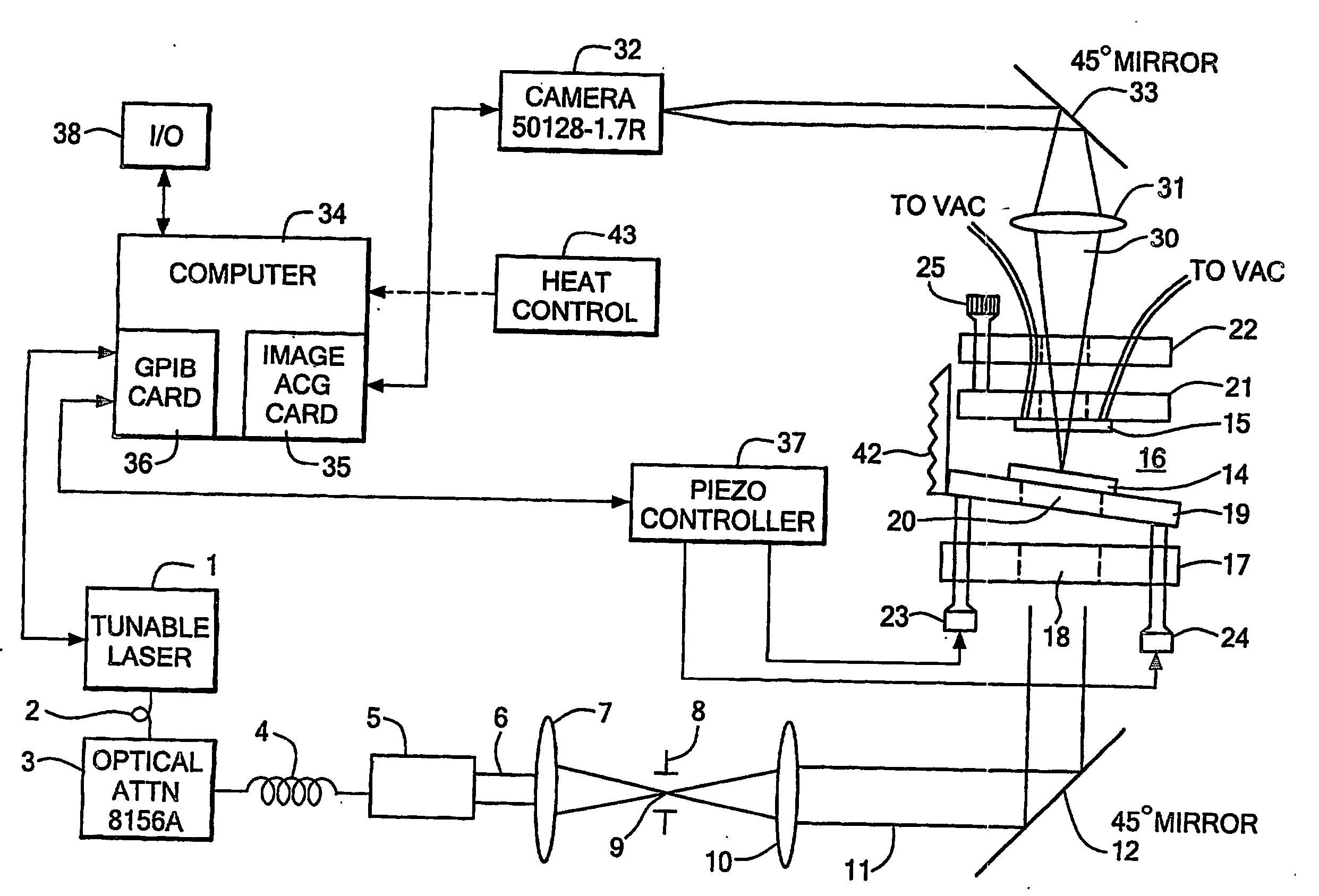
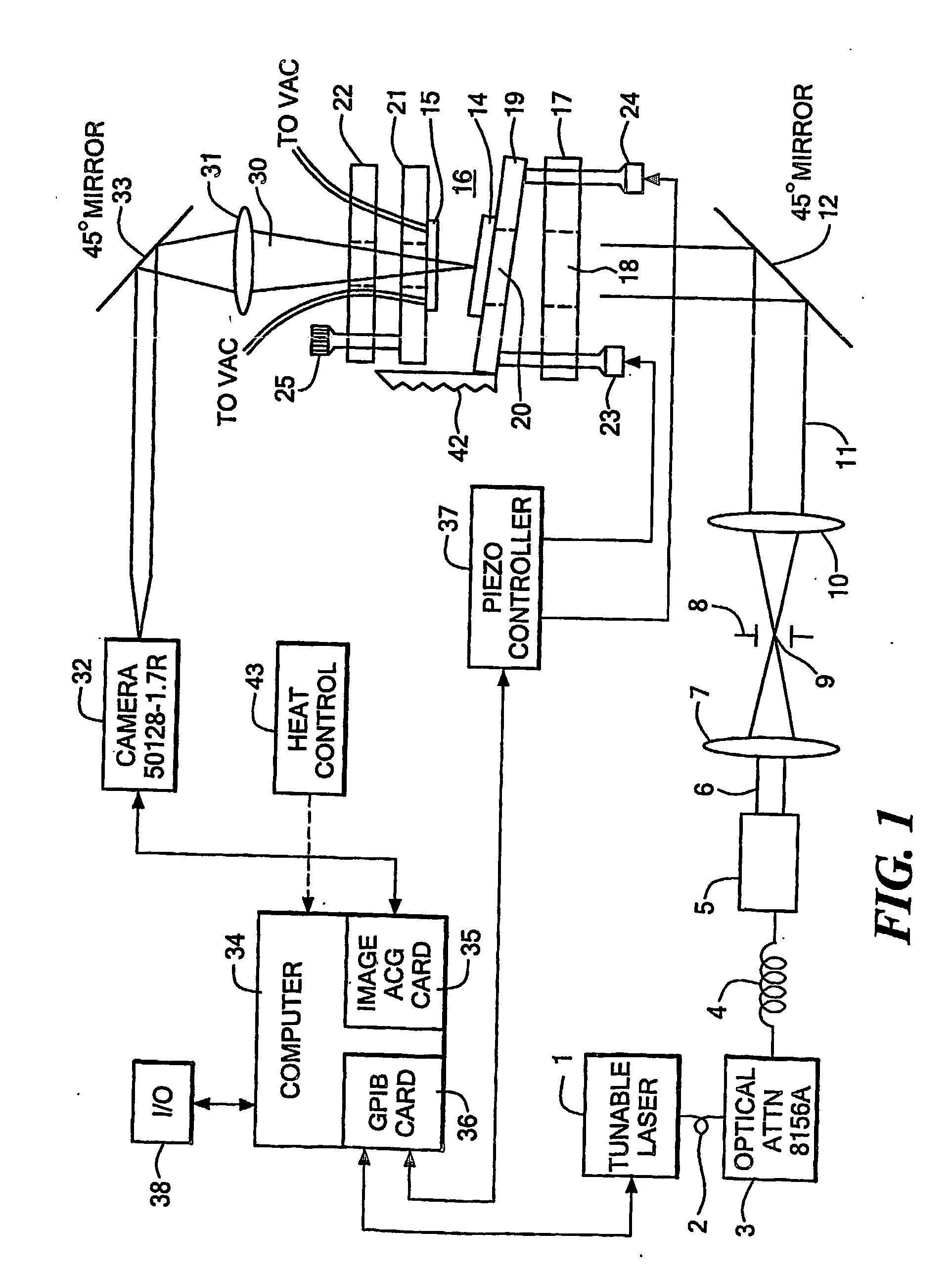
[0082] Fabrication of test sample: A test pattern has been fabricated in SiO2 to test that the system is working (FIG. 10A). 270 nm of SiO2 was deposited on the top surface of the first reflector. This SiO2 layer serves to place the sensing surface at a position in the cavity where the field strength is high (approximately 1 quarter wavelength out from the reflector surface at the wavelengths we are scanning at). The SiO2 surface was then masked and lightly etched to leave 4 square features. The 4 squares are 50 μm×50 μm and 30 μm apart. The pattern is repeated every 500 μm. The sample was masked at the boxes and wet etched everywhere else using HF to remove approximately 15 nm of material. 4 boxes 50 μm×50 μm×15 nm should remain on top of 255 nm SiO2, on top of the reflector.

[0083] Running experiment: Micrometers were used to position the reflectors close to each other to form the cavity. A z-stage was used to translate one of the reflectors to approximately 100 μm away from the o...


PUM


Abstract

An assay system having a channel bounded by first and second reflective surfaces adapted to accommodate a fluid material therebetween and defining a plurality of regions in an array between those surfaces with each region defining a resonant cavity and adapted to receive a capturing material on a surface thereof whereby a source of radiation illuminates each region to provide a standing wave of radiation of within the cavity indicative of binding of said capturing agent to material under investigation, a binding thereof being detected in response to radiation from each cavity indicative of a change in the standing wave pattern.

Description

CROSS REFERENCE TO RELATED APPLICATIONS [0001] This application claims priority to commonly assigned Provisional Application Ser. No. 60 / 445,970 filed Mar. 19, 2003. International Application No. PCT / US00 / 12287, filed 5 May 2000 is incorporated herein by reference.STATEMENT REGARDING FEDERALLY SPONSORED RESEARCH OR DEVELOPMENT [0002] N / A BACKGROUND OF THE INVENTION [0003] In bio-research, ecological testing, medical testing, drug testing and bio-weapon and hazards detections there is a need for rapid, simultaneous and real time detection of various agents. Typically the agents are provided in a fluid to a test structure, generally an array of some form in which capturing materials of diverse types capable of binding to one or more of the materials undergoing test and provided in the fluid medium. The binding is a result of an affinity that molecules or bio-molecules have for each other and includes the affinities of DNA, RNA, proteins, small molecules and other molecules. DNA arrays...

Claims


Application Information

Patent Timeline
IPC IPC(8): G01N21/00G01NG01N21/64
CPCB01L3/5027G01N21/0303G01N21/253G01N21/7746
Inventor UNLU, M SELIMBERGSTEIN, DAVID A.RUANE, MICHAEL F.GOLDBERG, BENNETT B.
Owner TRUSTEES OF BOSTON UNIV
Why Eureka
Try Eureka