Cutting tool made of surface-coated cemented carbide with hard coating layer exhibiting excellent wear resistance in high speed cutting operation of high hardness steel

a cemented carbide and cutting tool technology, applied in the direction of superimposed coating process, other chemical processes, instruments, etc., can solve the problems of significant lower al content and low hardness at high temperatures, and achieve excellent heat resistance, high hardness, and excellent wear resistance.

Active Publication Date: 2006-08-17
MITSUBISHI MATERIALS CORP
View PDF5 Cites 6 Cited by
  • Summary
  • Abstract
  • Description
  • Claims
  • Application Information

AI Technical Summary

Benefits of technology

[0030] The surface-coated cemented carbide tool of the present invention is provided with the hard coating layer having the (Ti, Al, Si)N layer. By forming the hard coating layer having the top layer and the bottom layer of single phase structure and forming the top layer in a structure having the thin layer A and the thin layer B stacked alternately one on another, it is made possible

Problems solved by technology

Meanwhile, practical use of the (Ti, Al, Si)N layer having Si content in a range from 25 to 35 atomic % requires it to include a predetermined proportion of Ti so as to ensure a req

Method used


Image

  • Cutting tool made of surface-coated cemented carbide with hard coating layer exhibiting excellent wear resistance in high speed cutting operation of high hardness steel
  • Cutting tool made of surface-coated cemented carbide with hard coating layer exhibiting excellent wear resistance in high speed cutting operation of high hardness steel
  • Cutting tool made of surface-coated cemented carbide with hard coating layer exhibiting excellent wear resistance in high speed cutting operation of high hardness steel

Examples


example 1

[0035] A WC powder, a TiC powder, a ZrC powder, a VC powder, a TaC powder, a NbC powder, a Cr3C2 powder, a TiN powder, a TaN powder and a Co powder, all having a mean particle size in a range from 1 to 3 μm, were prepared as material powders, and were mixed in proportions shown in Table 1, by means of a ball mill in wet process for 72 hours. After drying, the mixture was pressed into a green compact with a pressure of 100 MPa. The green compact was sintered by heating at a temperature of 1400° C. for 1 hour in vacuum of 6 Pa. The sintered material was subjected to honing process to form a cutting edge with a curvature of R 0.03, thereby making carbide substrates A-1 through A-10 made of WC-based cemented carbide having the tip configuration of CNMG120408 specified in ISO standard.

[0036] A TiCN powder (TiC / TiN=50 / 50 in weight proportion), a Mo2C powder, a ZrC powder, a NbC powder, a TaC powder, a WC powder, a Co powder and a Ni powder, all having a mean particle size in a range from...

example 2

[0064] A coarse WC powder having a mean particle size of 5.5 μm, a fine WC powder having a mean particle size of 0.8 μm, a TaC powder having a mean particle size of 1.3 μm, a NbC powder having a mean particle size of 1.2 μm, a ZrC powder having a mean particle size of 1.2 μm, a Cr3C2 powder having a mean particle size of 2.3 μm, a VC powder having a mean particle size of 1.5 μm, a (Ti, W)C powder (TiC / WC=50 / 50 in mass proportion) having a mean particle size of 1.0 μm and a Co powder having a mean particle size of 1.8 μm were prepared as material powder and were mixed in proportions shown in Table 7. Wax was added to this mixture and mixed in acetone in a ball mill for 24 hours. After drying under a reduced pressure, the material was pressed into green compacts of predetermined shape with a pressure of 100 MPa. The green compacts were heated at a rate of 7° C. per minute to a predetermined temperature in a range from 1370 to 1470° C. in vacuum of 6 Pa and were sintered while being he...

example 3

[0085] The three kinds of sintered round rods, having the diameter of 8 mm (used to form the carbide substrates C-1 through C-3), diameter of 13 mm (used to form the carbide substrates C-4 through C-6) and diameter of 26 mm (used to form the carbide substrates C-7 and C-8) made in Example 2 were ground to make carbide substrates (drills) D-1 through D-8 made of WC-based cemented carbide having 2-flute configuration with helix angle of 30 degrees, measuring 4 mm×13 mm (carbide substrates D-1 through D-3), 8 mm×22 mm (carbide substrates D-4 through D-6) and 16 mm×45 mm (carbide substrates D-7 and D-8) in diameter and length of the slot forming section.

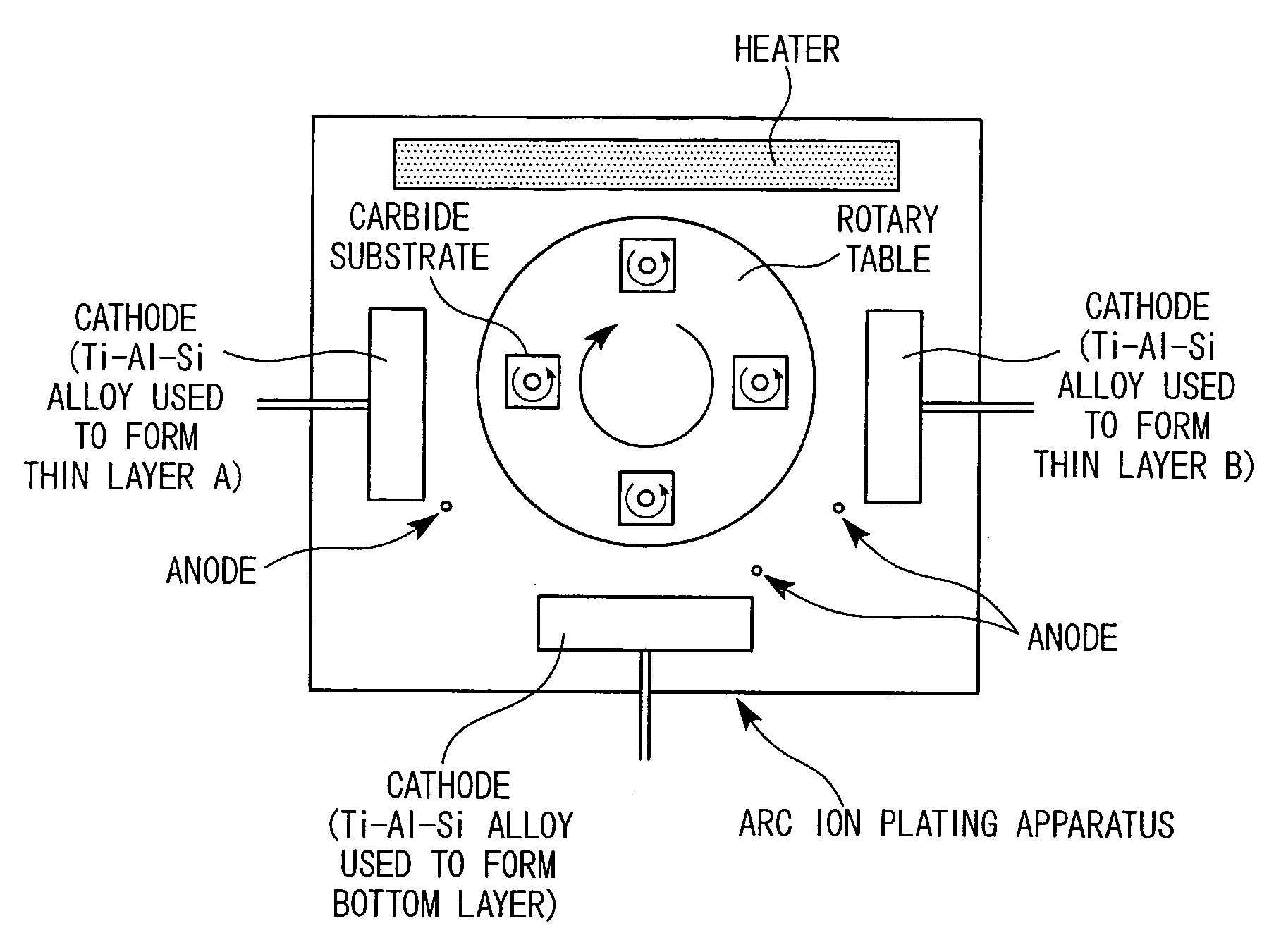
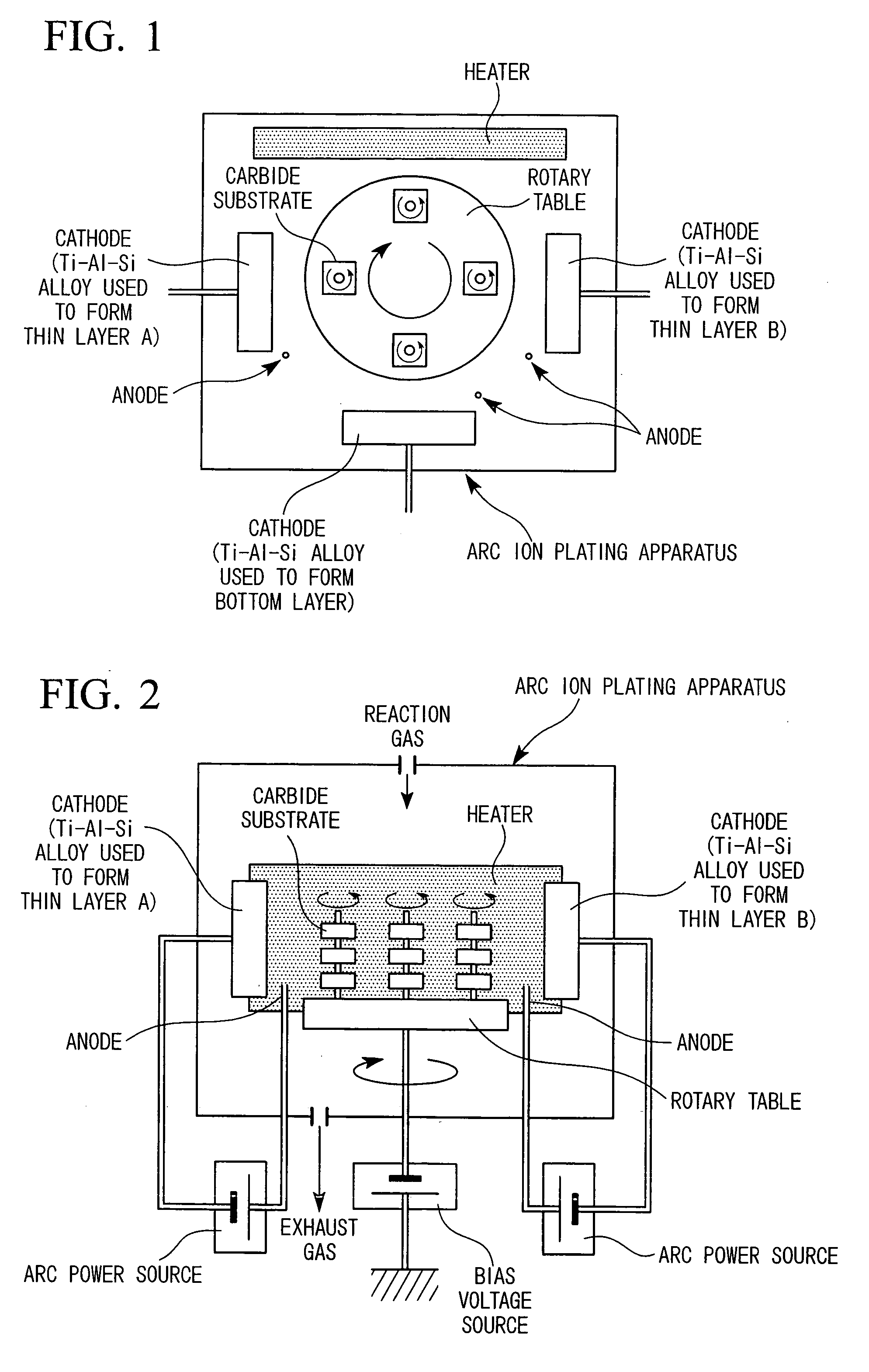
[0086] The carbide substrates (drills) D-1 through D-8 were subjected to honing of the cutting edge and were cleaned on the surface with ultrasound in acetone. After drying, the carbide substrates were set in an arc ion plating apparatus as shown in FIG. 1 and FIG. 2, and the bottom layer having (Ti, Al, Si)N layer of single phase struc...


PUM

PropertyMeasurementUnit
Lengthaaaaaaaaaa
Lengthaaaaaaaaaa
Nanoscale particle sizeaaaaaaaaaa

Abstract

A cutting tool made of surface-coated cemented carbide having the hard coating layer formed on the surface of a cemented carbide substrate, wherein the hard coating layer has a top layer and a bottom layer, the top layer includes a structure having the thin layer A and the thin layer B being stacked alternately, with the thin layer A having the composition of [Ti1-(A+B)AlASiB]N (A is in a range from 0.01 to 0.06 and B is in a range from 0.25 to 0.35 in an atomic ratio) and the thin layer B having the composition of [Ti1-(C+D)AlCSiD]N (C is in a range from 0.30 to 0.45 and D is in a range from 0.10 to 0.15), and the bottom layer comprises single phase structure having the composition of [Ti1-(E+F)AlESiF]N (E is in a range from 0.50 to 0.60 and F is in a range from 0.01 to 0.09).

Description

BACKGROUND OF THE INVENTION [0001] 1. Field of the Invention [0002] The present invention relates to a cutting tool made of surface-coated cemented carbide (hereinafter referred to as a surface-coated cemented carbide tool) provided with a hard coating layer that has excellent heat resistance, maintains high hardness and high strength at high temperatures and, as a consequence, exhibits excellent wear resistance even in high speed cutting operation of a high hardness steel, such as alloy tool steel or hardened bearing steel, which requires especially high heat resistance and generates much heat during the cutting operation. [0003] Priority is claimed on Japanese Patent Application No. 2005-035684, filed Feb. 14, 2005, the content of which is incorporated therein by reference. [0004] 2. Description of Related Art [0005] A surface-coated cemented carbide tool in general includes indexable insert that is removably attached at the tip of a cutting tool for machining of workpieces made o...

Claims


Application Information

Patent Timeline
IPC IPC(8): B32B9/00
CPCC23C30/005C23C28/044Y10T428/24975Y10T428/265C23C28/42A44B11/266A44B6/00
Inventor KONDO, AKIHIROTANAKA, YUSUKEMAEDA, KOICHI
Owner MITSUBISHI MATERIALS CORP
Why Eureka
Try Eureka