Mass spectrometer

a mass spectrometer and mass spectrometer technology, applied in the field of mass spectrometers, can solve the problems of unsuitable direct flow arrangement, unsuitable diameter columns, and relatively high flow rates, and achieve the effect of reducing the number of mass spectrometers

Inactive Publication Date: 2006-08-24
MICROMASS UK LTD
View PDF13 Cites 35 Cited by
  • Summary
  • Abstract
  • Description
  • Claims
  • Application Information

AI Technical Summary

Benefits of technology

[0073] The preferred embodiment advantageously enables an extended time to be spent analysing species or analytes of interest that elute from a liquid chromatography column thereby enabling the observed ion counts to be increased and the signal to noise ratio to be increased (or allowing more experiments to be performed when multiple components are co-eluting).
[0074] The preferred chromatography system comprises a liquid chromatograph pump with three pumping trays A,B,C. Two of the pumping trays A,B are preferably used for solvent gradient formation whilst the third C is preferably used for loading a sample and for elution at relatively lower flow rates. An advantage of the preferred chromatography system is that the preferred system does not require any restrictors to control the flow rate. Furthermore, a post-column valve is not required and is preferably not used so that the preferred system does not suffer from the detrimental effects to chromatographic performance caused by the introduction of a dead volume.
[0075] The preferred embodiment enables peak parking to be performed in an improved manner compared with other known approaches to peak parking. In particular, when the mass analyser, mass spectrometer or other analytical instrument identifies the presence of a species or analyte of interest, a pulse, signal or other indication is preferably sent to the liquid chromatography pump(s) A,B. The solvent gradient due to solvent channel A,B is then preferably halted, preferably substantially immediately, and the flow from the pump(s) A,B is preferably either reduced or substantially stopped altogether. A valve preferably switches which preferably has the effect of substantially removing (or less preferably significantly reducing) column head pressure. The valve also enables the sample flow from an auxiliary pump C operating at a lower flow rate to be directed to the column input. A low pressure build up then preferably occurs which causes the sample or analyte to pass through or elute from the analytical column at a relatively lower flow rate and effectively therefore creates a peak parking effect.
[0077] A particularly advantageous feature of the preferred embodiment is that the preferred liquid chromatography system does not suffer from pressure relaxation problems as the head pressure is preferably dissipated almost or substantially instantaneously. The column pressure is then preferably allowed to build up due to the flow rate of an auxiliary isocratic pump C operating at a relatively low flow rate. A further advantage of the preferred system is that no post-column valve is required and hence chromatographic resolution is maintained in the system.

Problems solved by technology

However, there are circumstances wherein a direct flow arrangement is unsuitable.
However, such large diameter columns commonly require relatively high flow rates of several millilitres per minute.
Relatively high flow rates may be particularly unsuitable for an Electrospray Ionisation ion source especially if the solvent mixture being used to push the sample through the analytical column contains a relatively high percentage or proportion of water.
However, since HPLC pumps are relatively poor at providing an accurate, stable and reproducible solvent gradient at such relatively low flow rates, it is known to run the pumps from solvent channels A,B at relatively higher flow rates but then to split the delivery flow before the nano-flow column so that only a much lower flow rate of delivery fluid passes through and on to the nano-flow HPLC column.
However, a limitation on the quality of data which can be achieved with low abundance species when using a liquid chromatography system coupled to a mass spectrometer is the relatively short time that any particular analyte species is actually present in the Electrospray Ionisation ion source.
This also has the effect that the number of different MS / MS product ion mass spectra which can be performed and recorded is limited by the length of time that any species of parent ion is present within the ion source.
However, this approach suffers from the problem that the pressure equilibration is not instantaneous.
Furthermore, the restrictors may become clogged causing differences in flow rate.
A yet further problem with the disclosed variable flow approach is that with narrow peak elution times e.g.
However, the use of a post-column valve leads to the introduction of a dead volume which is detrimental both to chromatographic performance and chromatographic resolution.
The known method of using a post-column valve to enable variable flow chromatography is therefore particularly disadvantageous.

Method used


Image

  • Mass spectrometer
  • Mass spectrometer
  • Mass spectrometer

Examples


Embodiment Construction

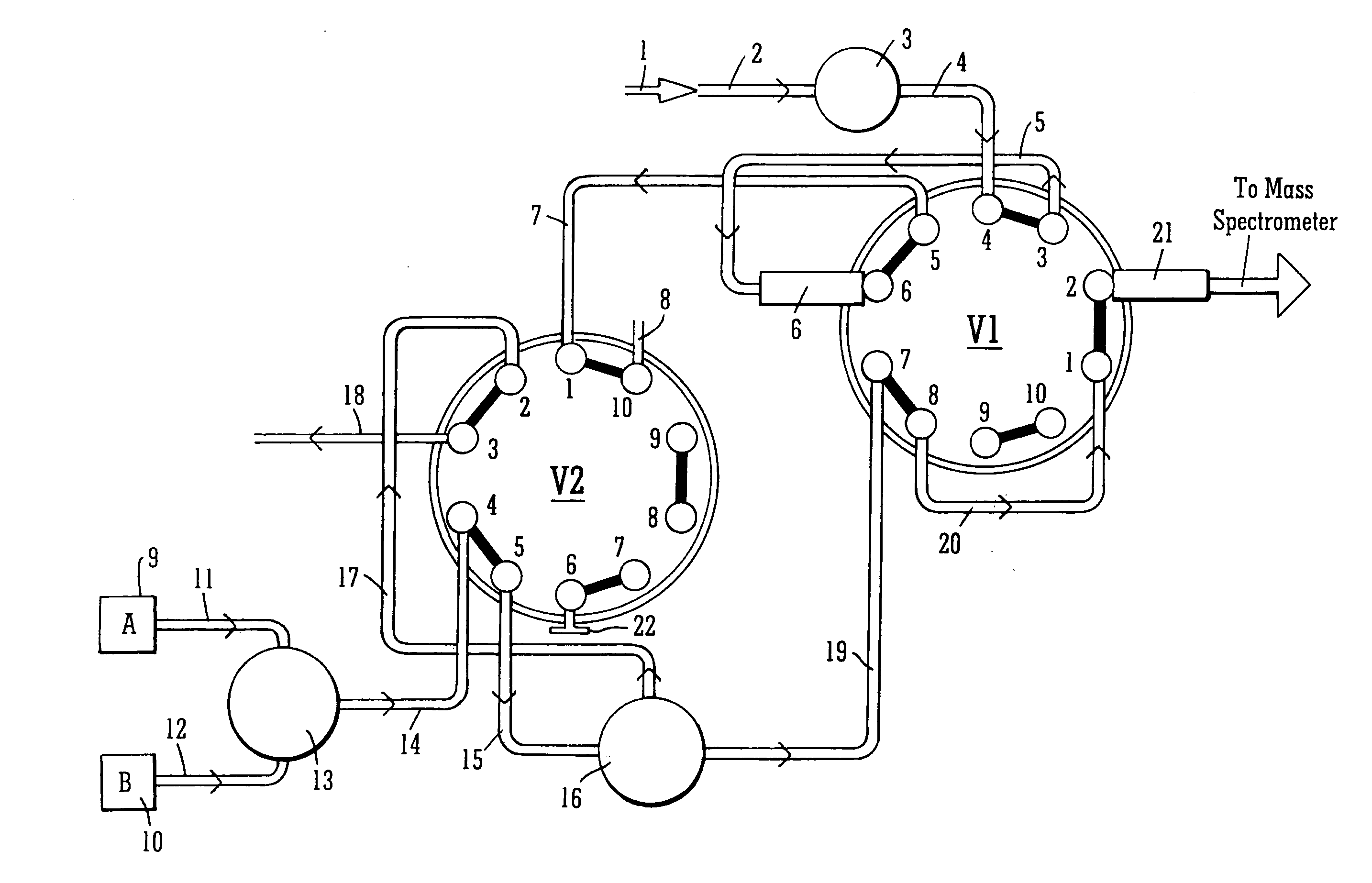
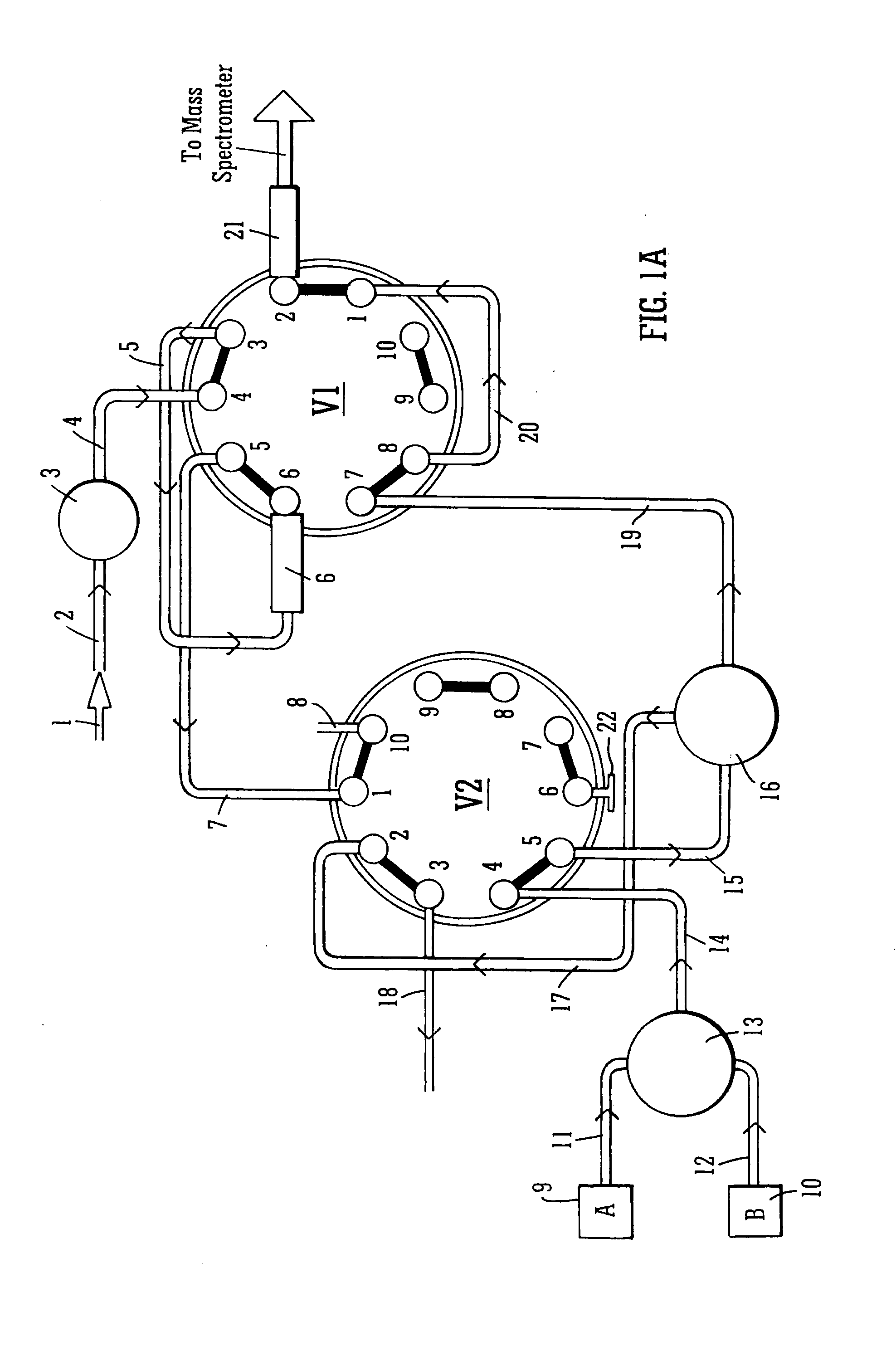
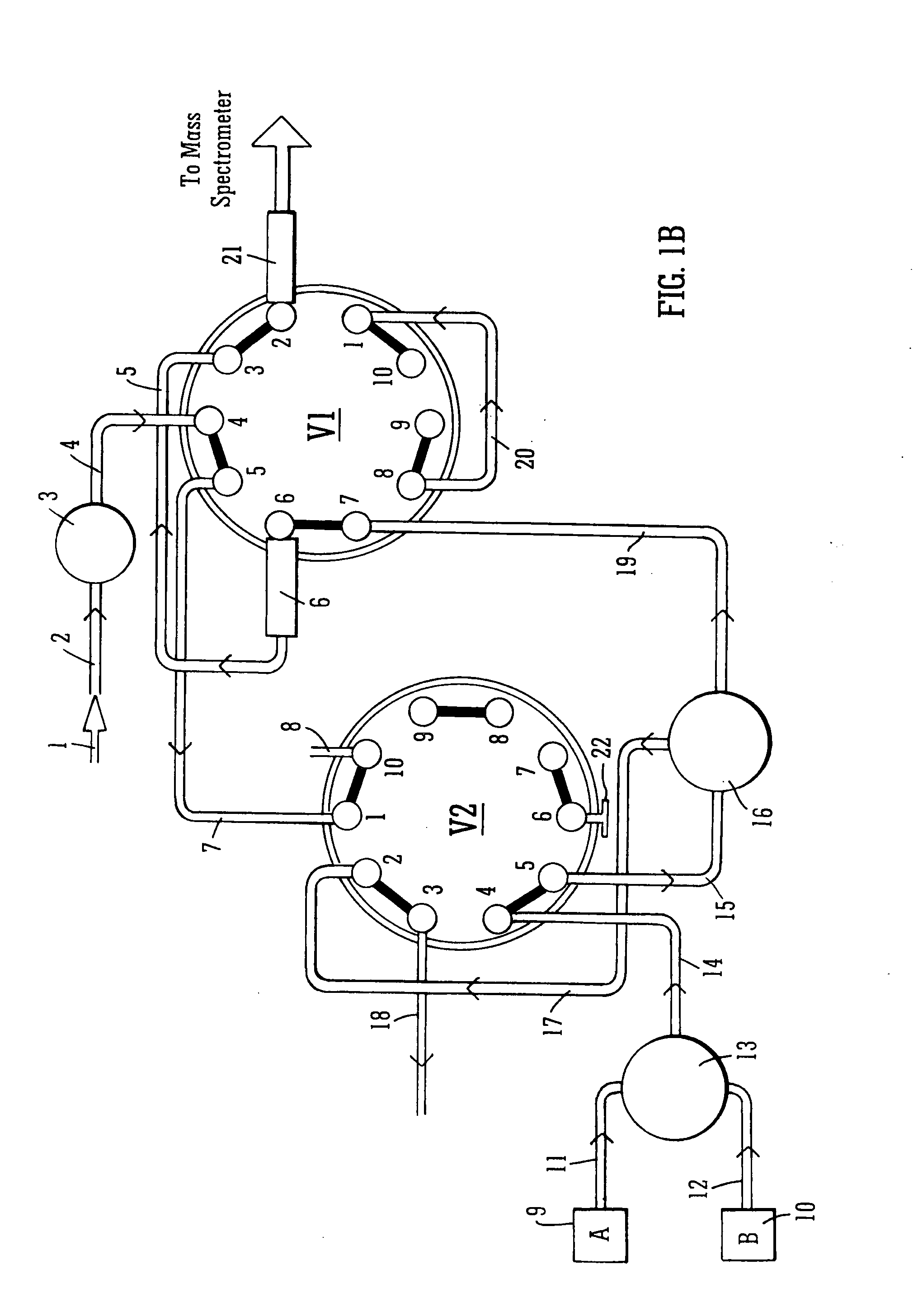
[0083] A preferred embodiment for implementing variable flow chromatography with a split flow chromatography system will now be described with reference to FIGS. 1A, 1B and 1C. The preferred chromatography system preferably comprises two ten-port switching valves V1,V2. Different sizes of tubing and capillaries may be used to implement the system. The valve rotor positions are indicated in each figure by thick lines. For example, with respect to valve V1 as shown in FIG. 1A, port 1 is connected to port 2, port 3 is connected to port 4, port 5 is connected to port 6, port 7 is connected to port 8, and port 9 is connected to port 10.

[0084] The split flow chromatography system as shown in FIGS. 1A, 1B and 1C may, for example, be used in conjunction with an analytical column 21 having an inside or internal diameter of 180 μm or less. The split ratio is preferably dependent upon the back pressure of a restrictor compared with the back pressure of a precolumn 6 plus analytical column 21....


PUM

PropertyMeasurementUnit
internal diameteraaaaaaaaaa
lengthaaaaaaaaaa
sizeaaaaaaaaaa

Abstract

A mass spectrometer and a liquid chromatography system for a mass spectrometer is disclosed. In a peak parking mode of operation solvent from A and B solvent pumps 9, 10 is immediately diverted to waste reducing the backpressure on an analytical column 21. Analyte of interest is then allowed to be released from the column 21 at a slower rate by passing fluid from a separate pump 1 through the column 21.

Description

CROSS REFERENCE TO RELATED APPLICATIONS [0001] This application claims priority from UK Patent Application No. GB 0402621.7 filed 6 Feb. 2004, UK Patent Application No. GB 0403289.2 filed 13 Feb. 2004 and U.S. Provisional Patent Application Ser. No. 60 / 543,889 filed 12 Feb. 2004. The contents of these applications are incorporated herein by reference. FIELD OF THE INVENTION [0002] The present invention relates to a liquid chromatography system, a mass spectrometer, a method of liquid chromatography and a method of mass spectrometry. BACKGROUND OF THE INVENTION [0003] Liquid chromatography is a method by which various species from a complex mixture can be separated out into their individual components. The individual species or components will elute from the liquid chromatography system at substantially different times. [0004] Known liquid chromatography systems include High Performance Liquid Chromatography (HPLC) systems incorporating a pumping system which comprises two solvent ch...

Claims


Application Information

Patent Timeline
Patent Type & Authority Applications(United States)
IPC IPC(8): B01D15/08
CPCG01N30/02G01N30/10G01N30/32G01N30/7233B01D15/325G01N2030/324B01D15/163
Inventor HUGHES, CHRIS
Owner MICROMASS UK LTD
Why Eureka
Try Eureka